International Journal of Robotic Engineering
(ISSN: 2631-5106)
Volume 6, Issue 1
Research Article
DOI: 10.35840/2631-5106/4136

Article Formats
Optimal Design of Biped Amble Mechanism using Matlab
Table of Content
Figures
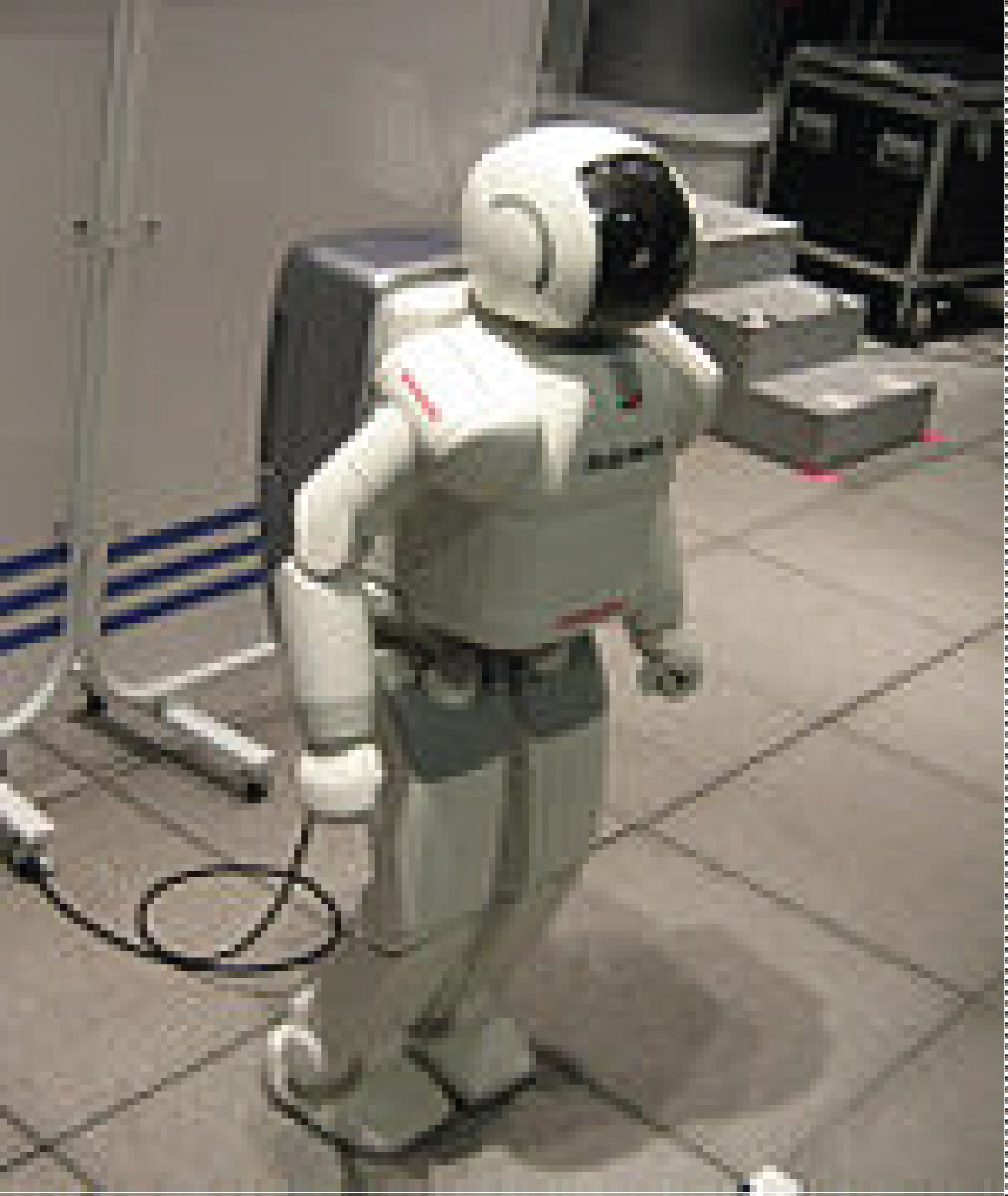
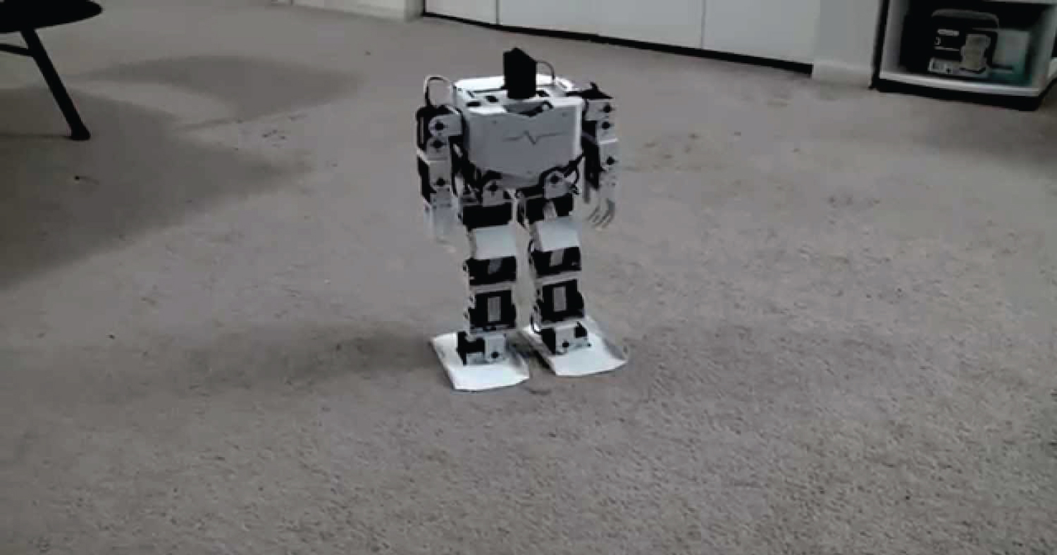
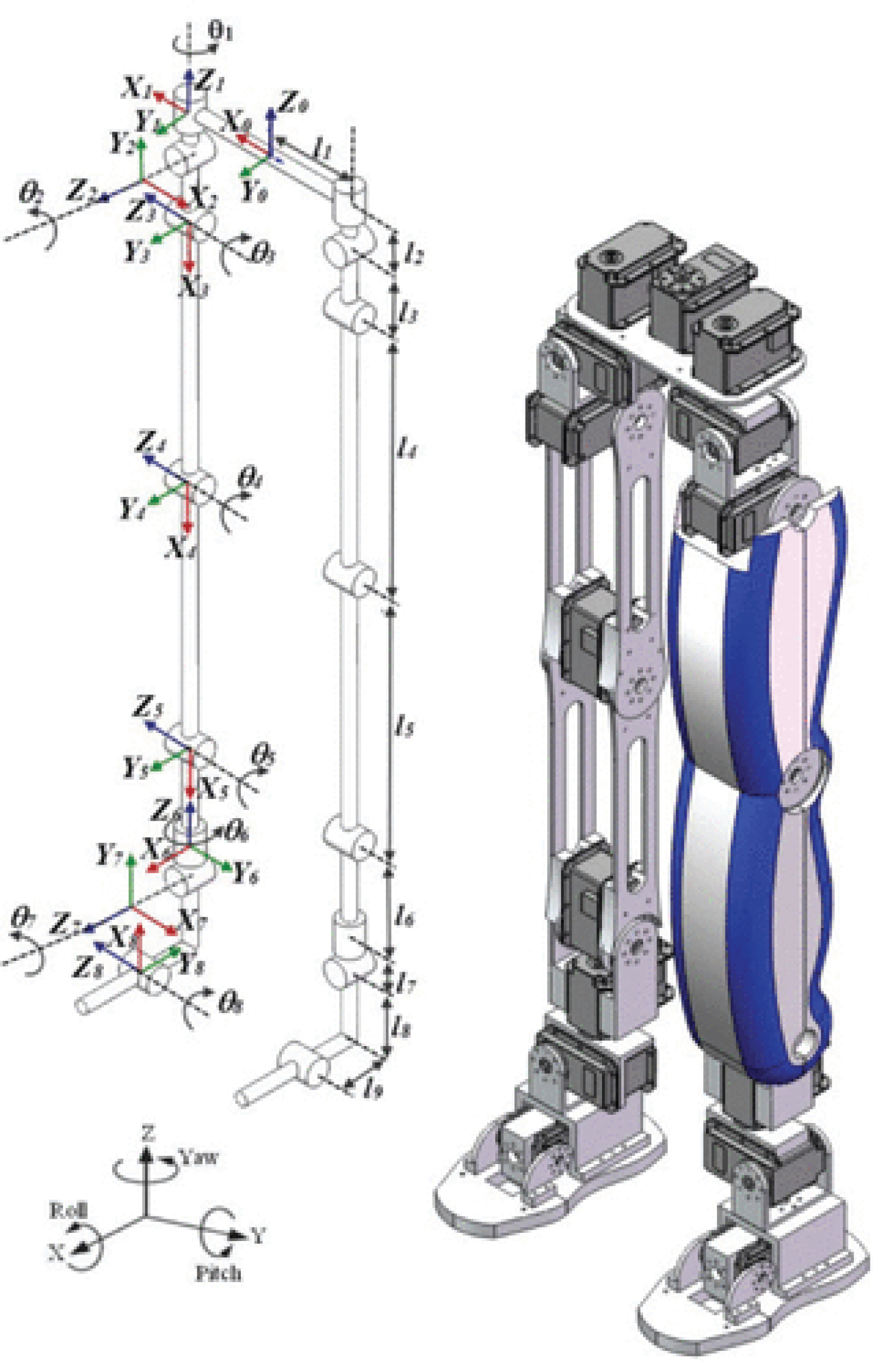
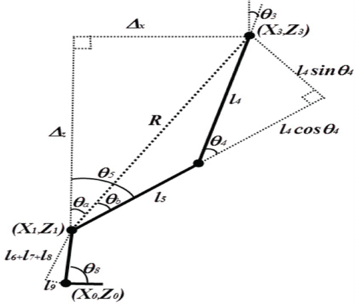
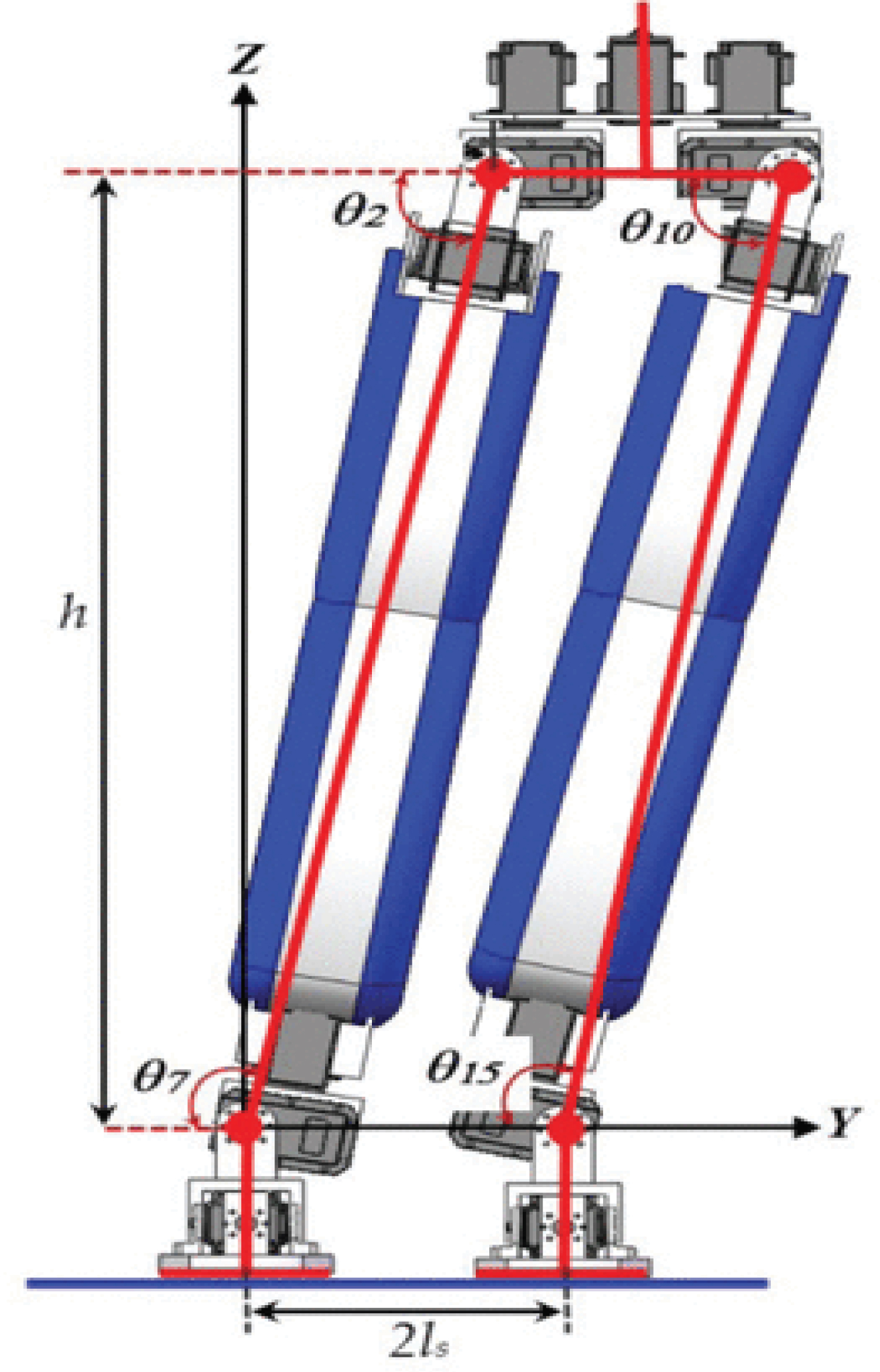
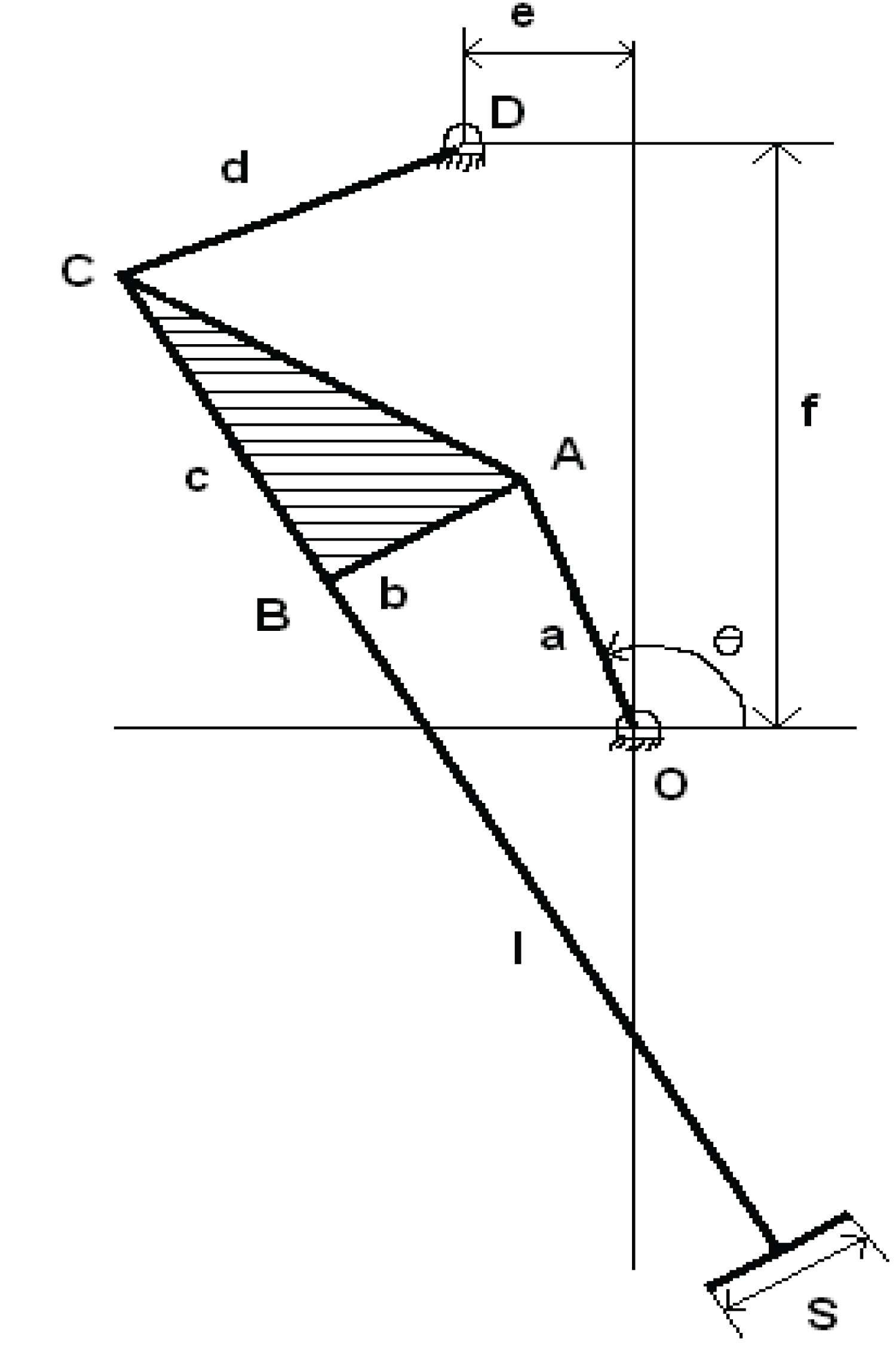
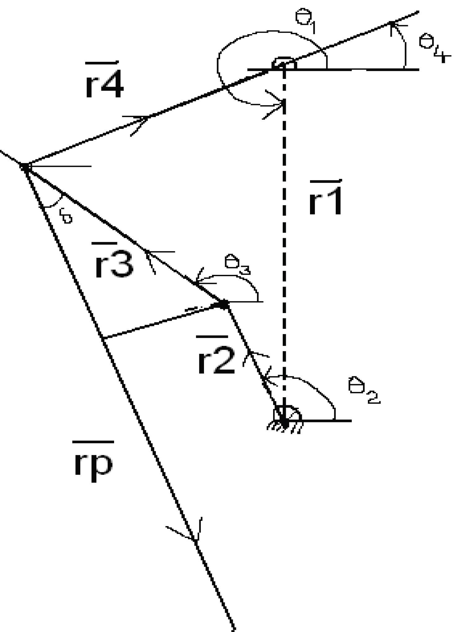
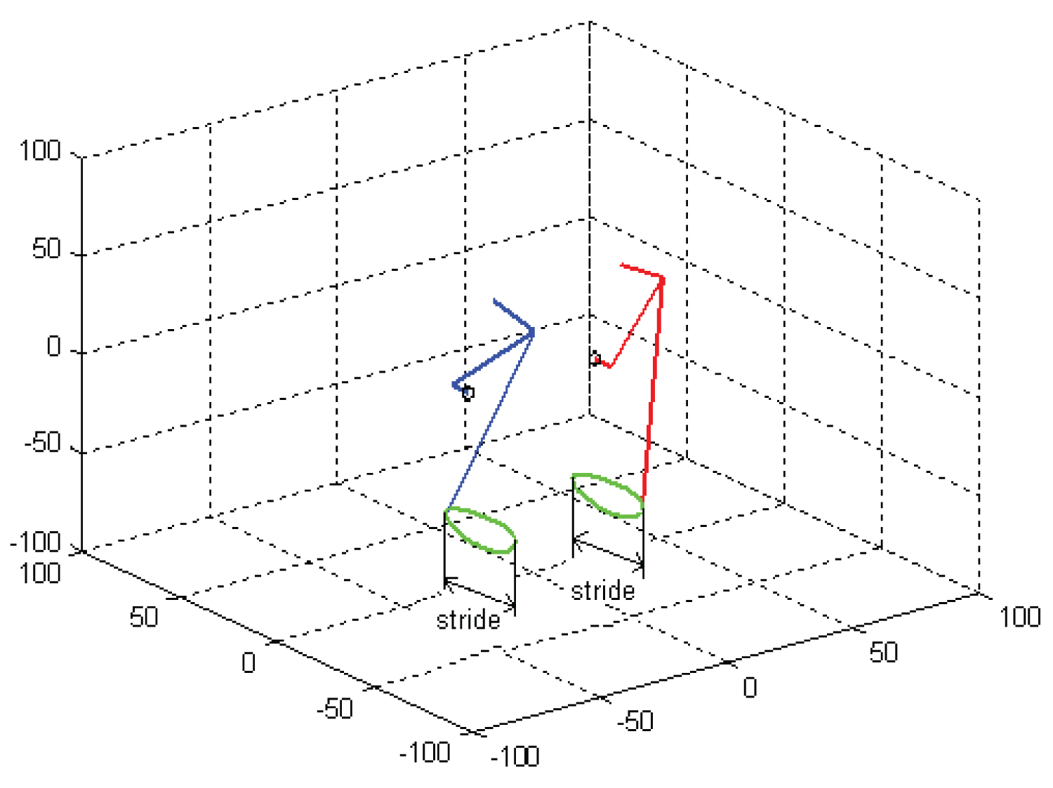
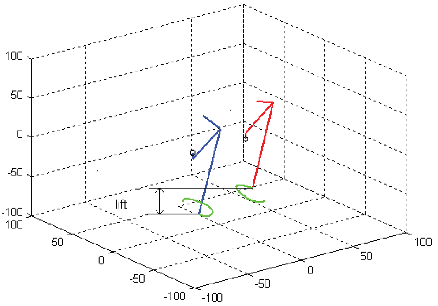
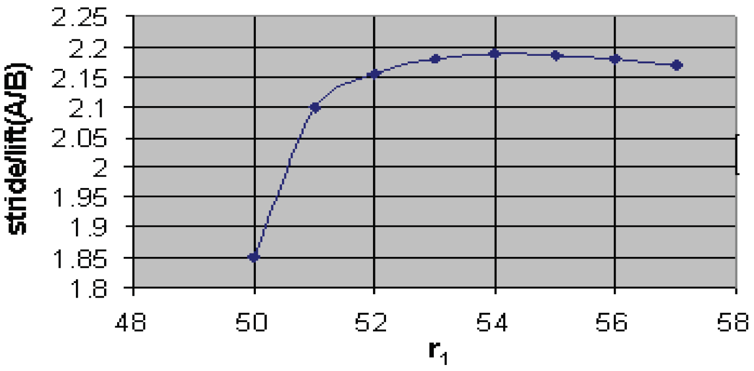

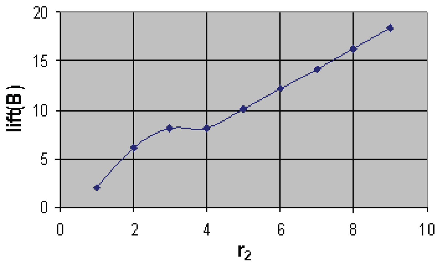
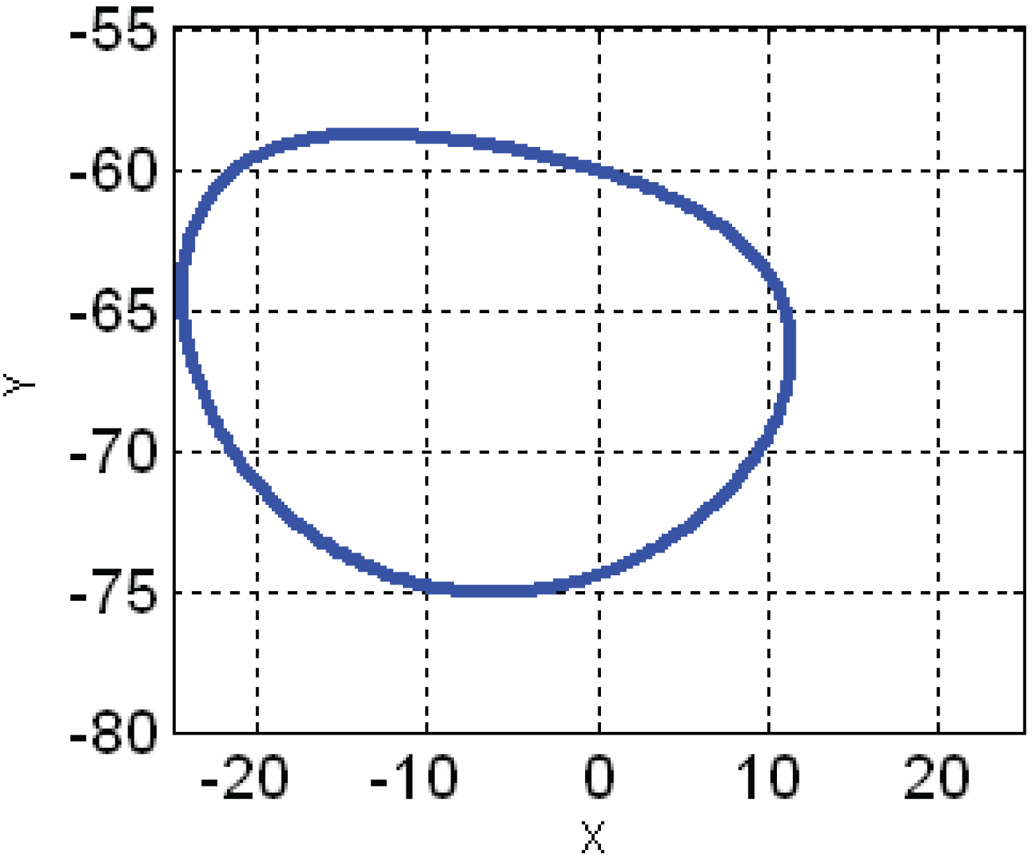
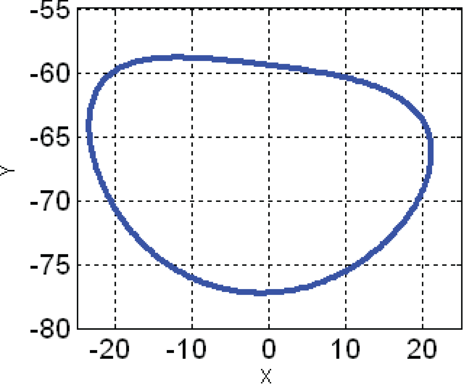
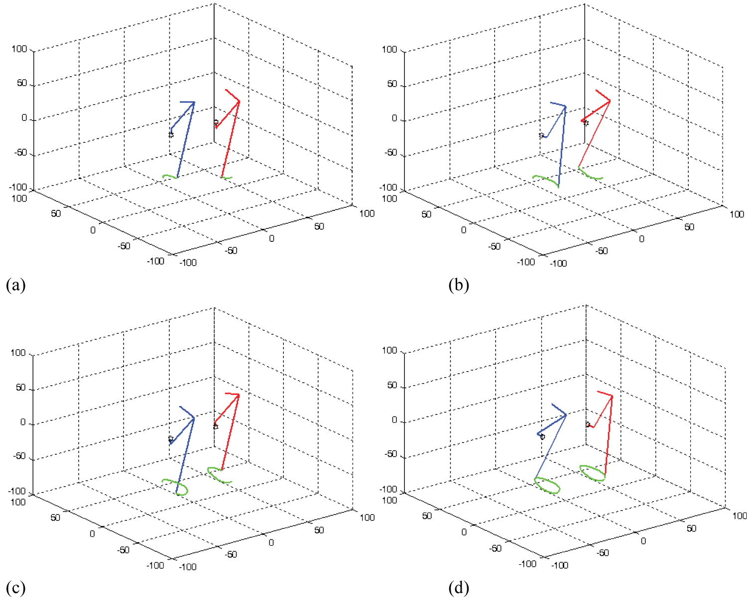
Figure 15: Trajectory of foot of both....
Trajectory of foot of both the legs of the biped mechanism while moving.
Tables
Table 1: 'K' values for different styles of gait.
Table 2: Performance characteristics of the model.
Table 3: Optimal dimensions of the mechanism for various styles of walking.
Table 4: Performance characteristics, considering optimized dimensions, for various styles of walking.
References
- Sushant S, Deivanathan R (2014) Optimum linkage for biped mechanism. VIT University 97: 1322-1331.
- Kyosuke O, Ryutaro T, Toru S, Atsushi I (2001) Self-excited walking of a biped mechanism. International Journal of Robotics Research 20: 953-966.
- Katla M, Ravi KM, Pandu RV (2018) An efficient path planning algorithm for biped robot using fast marching method. Procedia Computer Science 133: 116-123.
- Roopa N, Ayesha S, Avirup G, Vivekanada S (2020) Simulation and Modeling of 6-DOF Biped Mechanism. Indian Journal of Science and Technology 8: 185-188.
- Naomichi O, Eishi H, Emanuel A, Reinhard B (2018) Bipedal gait versatility in the japanese macaque (Macaca fuscata). Journal of Human Evolution 125: 2-14.
- Satoshi I, Shingo N, Masaaki I, Ryosuke M, Kojiro M, et al. (2018) Design and adaptive balance control of a biped robot with fewer actuators for slope walking. Mechatronics 49: 56-66.
- Taisuke K, Kosuke S, Yasuhisa H, Tadayoshi A, Toshio F (2018) Unified bipedal gait for autonomous transition between walking and running in pursuit of energy minimization. Graduate School of Information Science, Nara Institute of Science and Technology, Nara, Japan.
- Xiangxiao L, Yu D, Arne H, Yuntong X, Tsungyuan C, et al. (2018) Using the foot windlass mechanism for jumping higher: A study on bipedal robot jumping. Robotics and Autonomous Systems 110: 85-91.
- Christine A, Nicolás A, Soraya A (2004) BIPedal walking: From gait design to experimental analysis. Mechatronics, Elsevier 14: 639-665.
- R Chakraborty, GC Nandi, S Kundu (2016) Component based computational model for bipedal locomotion. Robotics and Autonomous Systems, 48-56.
- Fumiy A, Yohei M, Jürgen R, André S (2009) Toward a human-like biped robot with compliant legs. Robotics and Autonomous Systems 57: 139-144.
- Taesin HA, Chong H (2007) An effective trajectory generation method for bipedal walking. School of Electrical Engineering and Computer Science, Seoul National University 55: 795-810.
- Filipe MS, TenreiroMachado JA (1998) Dynamic efficiency during bipedal walking. Dept of Electrical and Computer Engineering Faculty of Engineering of the University of Porto, Portugal.
Author Details
Roopsandeep Bammidi1*, Raghuveer Dontikurti1, Dowluru Sreeramulu2, C J Rao2 and A Satish Kumar3
1Assistant Professor, Department of Mechanical Engineering, Aditya Institute of Technology and Management, India
2Professor, Department of Mechanical Engineering, Aditya Institute of Technology and Management, India
3Department of Mechanical Engineering, Aditya Institute of Technology and Management, India
Corresponding author
Roopsandeep Bammidi, Assistant Professor, Department of Mechanical Engineering, Aditya Institute of Technology and Management, Tekkali, India.
Accepted: December 17, 2021 | Published Online: December 19, 2021
Citation: Bammidi R, Dontikurti R, Sreeramulu D, Rao CJ, Kumar AS (2021) Optimal Design of Biped Amble Mechanism using Matlab. Int J Robot Eng 6:036.
Copyright: © 2021 Bammidi R, et al. This is an open-access article distributed under the terms of the Creative Commons Attribution License, which permits unrestricted use, distribution, and reproduction in any medium, provided the original author and source are credited.
Abstract
From past decades, the different types of mechanisms in mobile robots have been created so far which includes legged, treaded-tyre and wheeled type robots. Among these types, the wheeled type is easiest to control while the treaded-tyre type offers improved flexibility. Legged locomotion, though not widely used for industrial purposes, has growing implications mainly due to its ease of maneuvering in rough terrains. The Walking motion is obtained through various mechanisms. It is the crank and rocker mechanism, which gives a walking style characteristic of human being. The present research work uses a different type of mechanism for driving a biped that is most distinguished by its ease of operation that produces a type of 'walk' similar to two legged mammals. In this research initially, a multi-objective optimization is carried out for the optimal design of the mechanism. This research involves a simulation of a simple Biped model using Crank-Rocker mechanism. The design of the biped robot is done by considering two important objective parameters stride and lift, a multi objective function must be created and optimization is done by using MATLAB Programming.
Keywords
BAM (Biped Amble Mechanism), Crank and rocker mechanism, MATLAB, Biped robot, Multi-objective optimization, Stride and lift
Introduction
A robot is a mechanical device that can perform physical tasks. A robot may act under the direct control of a human like the robotic arm of the space shuttle or autonomously under the control of a pre-programmed computer. Robots may be used to perform tasks that are too difficult for humans to do directly (e.g. the space shuttle arm) or may be used to automate repetitive tasks that can be performed more cheaply by a robot than by the employment of a human for example automobile production. The word robot is used to refer to a wide range of machines, the common feature of which is that they are all capable of movement and can be used to perform physical tasks. Robots take on many different forms, ranging from Humanoid which mimic the human form and way of moving, to industrial, whose appearance is dictated by the function they are to perform. Robots can be grouped generally as mobile robots like autonomous vehicles, manipulator robots like Industrial robots and self re-configurable robots, which can conform themselves to the task at hand. Robots may be controlled directly by a human, Such as remotely controlled bomb-disposal robots, robotic arms, or shuttles, or may act according to their own decision-making ability, provided by artificial intelligence. However, the majority of robots fall in between these extremes, being controlled by preprogrammed computers. Such robots may include feedback loops such that they can interact with their environment, but do not display actual intelligence. The word robot is also used in a general sense to mean any machine that mimics the actions of a human (bio-mimicry) in the physical sense or in the mental sense. There are many possible robot "drive" systems, or how the robot moves. There are of course certain advantages and disadvantages to each. It depends on the application of the robot, and what its needs are. The wheeled robots are robots that navigate around the ground using motorized wheels to propel themselves. This design is simpler than using treads or legs and by using wheels they are easier to design, build, and program for movement in flat, not-so-rugged terrain. They are also better controlled than other types of robots. Disadvantages of wheeled robots are that they cannot navigate well over obstacles, such as rocky terrain, sharp declines, or areas with low friction. The two wheeled robots are harder to balance than other types because they must keeping moving to maintain upright. The center of gravity of the robot body is kept below the axle; usually this is accomplished by mounting the batteries below the body. They can have their wheels parallel to each other. The 3-wheeled robots may be of two types: Differentially steered (2 powered wheels with an additional free rotating wheel to keep the body in balance) or 2 wheels powered by a single source and a powered steering for the third wheel. In the case of differentially steered wheels, the robot direction may be changed by varying the relative rate of rotation of the two separately driven wheels. If both the wheels are driven in the same direction and speed, the robot will go straight. Otherwise, depending on the speed of rotation and its direction, the center of rotation may fall anywhere in the line joining the two wheels? The center of gravity in this type of robot has to lay inside the triangle formed by the wheels. If too heavy of a mass is mounted to the side of the free rotating wheel, the robot will tip over. The 4-wheeled vehicles like two powered, two free rotating wheels; Same as the differentially steered ones above but with 2 free rotating wheels for extra balance. More stable than the three wheel version since the center of gravity has to remain inside the rectangle formed by the four wheels instead of a triangle. This leaves a larger useful space. Still it's advisable to keep the center of gravity to the middle of the rectangle as this is the most stable configuration, especially when taking sharp turns or moving over a non-level surface (Figure 1).
Bipedal or two-legged robots exhibit Bipedal Motion. As such, they face two primary problems:
1. Stability control, which refers to a robot's balance, and
2. Motion control, which refers to a robot's ability to move.
Stability control is particularly difficult for bipedal systems, which must maintain balance in the forward-backward direction even at rest. Some robots, especially toys, solve this problem with large feet, which provide greater stability while reducing mobility. Alternatively, more advanced systems use sensors such as accelerometers or gyroscopes to provide dynamic feedback in a fashion that approximates a human being's balance. Such sensors are also employed for motion control and walking. The complexity of these tasks lends itself to machine learning. Simple bipedal motion can be approximated by a rolling polygon where the length of each side matches that of a single step. As the step length grows shorter, the number of side's increases and the motion approaches that of a circle. This connects bipedal motion to wheeled motion as a limit of stride length. The bi-pedalism is a form of terrestrial locomotion where an organism moves by means of its two rear limbs or legs. An animal or machine that usually moves in a bipedal manner is known as a biped meaning "two feet" Types of bipedal movement include walking, running, or hopping. A robot with its body shape built to resemble the human body. The design may be for functional purposes, such as interacting with human tools and environments, for experimental purposes, such as the study of bipedal locomotion, or for other purposes (Figure 2).
The Locomotion of a robot has been achieved with many possible solutions like legged or wheeled type. But the optimum linkage mechanism for a biped robot is yet to be specified for the purpose of walking. In this paper, different types of linkages depending upon their degree of freedom (DOF) have been compared and the best of them have been selected with help of ADMAS software. The biped mechanism consists of only two legs that are connected at the hip joint and are used for the locomotion of the robot/humanoid. This mechanism is selected based on parameters which are force developed in joints, trajectory of center of mass (COM) of links and kinetic energy attained by all the links [1]. This paper presented a self-excited walking of a four link biped mechanism which possesses an actuated hip joint and passive knee joints. First we manifested that this self-excitation control enables 3-DOF planar biped model to walk on a level ground, by numerical simulation. Next, we showed experimental study of a manufactured planar biped walking robot. We demonstrated that stable walking can be realized on a slightly inclined plane by the self-excitation control using simple analytical model and basic equation in each phase, we numerically showed self-excited biped walking. As a result, it was found that stable walking motion is possible over the wide range of feedback gain. The walking velocity and period were not so affected by feedback gain because this control strategy utilized the natural motion of the biped mechanism [2]. An efficient path planning algorithm is required for the robot to move in a complex known and unknown environment. In the present research, the authors made an attempt to develop a path planning algorithm, that is, fast marching method (FMM) for the biped robot to move in a static environment. Once the path planning algorithm is developed, a simulation study is conducted to determine the path for the environment that consists of different number of obstacles that from different configurations for the terrain. The path planning algorithm is successfully seen to derive collision-free shortest paths in all the cases. Further, experiments are conducted on a real biped robot to test the effectiveness of the algorithm in deriving on-line collision-free path for the robot [3]. An approach of designing and implementing walking postures for bipedal robot. The project presents efficient mechatronics architecture describing mechanical to software issues related to designing and execution of locomotion. The aim is to simulate and exhibit the robustness and the efficiency of the controller architecture using PD controller in MATLAB. The mission is to develop a biped to walk using Arduino Mega 2560.PRO-E simulation is done to calculate motion parameters. Trajectory planning is accomplished using MATLAB [4]. It was previously believed that, among primates, only humans run bipedal. However, there is now growing evidence that at least some non-human primates can not only run bipedal but can also generate a running gait with an aerial phase. Japanese macaques trained for bipedal performances have been known to exhibit remarkable bipedal locomotion capabilities, but no aerial-phase running has previously been reported. In the present study, we investigated whether Japanese macaques could run with an aerial phase by collecting bipedal gait sequences from three macaques on a level surface at self-selected speeds (n ¼ 188). During our experiments, body kinematics and ground reaction forces were recorded by a motion-capture system and two force plates installed within a wooden walkway. Our results demonstrated that macaques were able to utilize a variety of bipedal gaits including grounded running, skipping, and even running with an aerial phase. The self-selected bipedal locomotion speed of the macaques was fast, with Froude speed ranging from 0.4 to 1.3. However, based on congruity, no single trial that could be categorized as a pendulum-like walking gait was observed. The parameters describing the temporal, kinematic, and dynamic characteristics of macaque bipedal running gaits follow the patterns previously documented for other non-human primates and terrestrial birds that use running gaits but are different from those of humans and from birds' walking gaits. The present studies confirmed that when a Japanese macaque engages in bipedal locomotion, even without an aerial phase, it generally utilizes a spring-like running mechanism because the animals have a limited ability to stiffen their legs. That limitation is due to anatomical restrictions determined by the morphology and structure of the macaque musculoskeletal system. The general adoption of grounded running in macaques and other non-human primates, along with its absence in human bipedal locomotion, suggests that abandonment of compliant gait was a critical transition in the evolution of human obligatory bipedalism [5]. Although reducing the number of actuators in mobile robots contributes to weight saving and results in high efficiency or damage reduction in the event of an accident such as falling over, ideally it should not degrade the robot's performance and functionality. In this study, we propose a new biped mechanism that reduces the number of actuators in a robot without sacrificing its ability to walk adaptively on slopes. We address two issues from both the mechanical and the control viewpoints that are required to achieve straight walking on slopes. For the biped mechanism, we studied the required degrees of freedom of the biped robot and then proposed an actuation mechanism for the hip joint structure. Subsequently, we designed and constructed a biped robot with six actuators, including two actuators for each ankle, no knees, and two actuators for the hip joint structure. For control, we applied feedback from the center of pressure of the ground reaction forces in addition to gravity compensation and discussed the stability of movement. Experiments conducted using the constructed biped robot with fewer actuators demonstrated the viability of the proposed mechanism in terms of walking on slopes and the effectiveness of the proposed control concept, which introduces adaptability to the biped robot [6]. The paper addresses ''unified bipedal gait'' control, which autonomously selects the energy-minimized gait from walking and running at any feasible gait speeds. Humans select walking/running at low/high speed in pursuit of energy minimization and transition between them naturally. Despite the quite different behaviors of walking and running, human gaits share an inherent controller. The unified bipedal gait uses the inherent controller, which implements passive dynamic autonomous control (PDAC) based on a damping and spring-loaded inverted pendulum (D-SLIP) model. Although this D-SLIP could cause chaotic motions, compliance in the D-SLIP dynamics switches behaviors between walking and running, that is, low/high compliant legs for walking/running. This property is employed by the virtual holonomic constraint of the PDAC to extract the required characteristics of walking/running from the D-SLIP dynamics while restraining the chaotic motions for asymptotic stability. As a result, the unified bipedal gait bifurcates to walking and running via autonomous transition to minimize energy cost at any feasible gait speeds [7]. Both scientists and roboticists widely agree that the musculoskeletal system of the human foot plays an important role in locomotion. Nevertheless, the contribution of the foot musculoskeletal system has not been fully uncovered because currently it is impossible to modify and evaluate Musculo skeletons in living animals. Here, to understand the effects of foot windlass mechanism, we construct a bipedal robot, which has similar Musculo skeletons and dynamics to those of human. By implementing experiments on this robot, we investigate the effects (e.g. jumping height) of foot windlass mechanism on drop jumping, a simple and representative bouncing gait comprising landing and push-off [8]. The purpose of this study is to simulate the motion of the lower extremity of a human being, a biped mechanism, walking along a straight path and to suggest a control strategy for minimizing the deviation from the linear path. A "gait" function is defined as a control that ensures that the biped walks along a straight path. By varying some parameters associated with the "gait" functions, which is chosen in such a manner as to simulate the motion of one member of the biped relative to an adjoining member, the most suitable combinations of such parameters for the specified geometry is subsequently determined. The study contributes to a better understanding in the design of robots, humanoids, and other artificial intelligence (A.I.) systems [9]. Bipedal locomotion has been an active area of research for many decades, it has wide ranging applications in the field of humanoid locomotion, as well as in the understanding of the biomechanics of normal human gait. Inherently human gait is a complex non-linear dynamic system, which is usually modeled by a set of differential equations satisfying a given set of constraints. In this paper an attempt has been made to view gait from the perspective of software engineering. In doing so, the entire gait cycle has been discretized into phases and sub-phases and modeled using a hybrid automaton, subsequently the automaton has been integrated with the BIP (Behavior, Interaction, and Priority) framework, thereby creating a component based computational framework for modeling biped locomotion. The correctness of the developed model has been validated and verified through simulation runs in open sim [10]. The conventional models of bipedal walking generally assume rigid body structures, while elastic material properties seem to play an essential role in nature. On the basis of a novel theoretical model of bipedal walking, this paper investigates a model of biped robot which makes use of minimum control and elastic passive joints inspired from the structures of biological systems. The model is evaluated in simulation and a physical robotic platform by analyzing the kinematics and ground reaction force. The experimental results show that, with a proper leg design of passive dynamics and elasticity, an attractor state of human-like walking gait patterns can be achieved through extremely simple control without sensory feedback. The detailed analysis also explains how the dynamic human-like gait can contribute to adaptive biped walking [11]. The paper presents the virtual height inverted pendulum mode (VHIPM), which is a simple and effective trajectory generation method for the stable walking of biped robots. VHIPM, which is based on the inverted pendulum mode (IPM), can significantly reduce the zero, moment point (ZMP) error by adjusting the height in the inverted pendulum. We show the relationship between VHIPM and other popular trajectory generation methods and compare the ZMP errors in walking when trajectories are generated by various methods including VHIPM. We also investigate the sensitivity of the ZMP error in VHIPM to the step length, walking period and mass distribution of a robot. The simulation results show that VHIPM significantly reduces the ZMP errors compared to other methods under various circumstances [12]. The paper presents the energy analysis of a bipedal walking system. The main purpose is to gain insight into the movement strategies in walking and to search for the optimal locomotion variables that minimize a cost function related to energy. In order to accomplish this goal, three performance indices are proposed: Mean absolute power, mean power dispersion and mean power lost. At the same time, the description of the movement is based on a set of locomotion variables, namely: Step length, hip height, hip ripple, hip offset, and foot clearance and link lengths. The simulation results show the influence of these variables in the energy flow. The performance measures are discussed and the results compared with those observed in human locomotion [13].
Grashof's Theorem
The motion characteristics of a-four-bar mechanism will depend on the ratio of the link length dimensions. The links that are connected to the fixed link can possibly have two different types of motion: The link may have a full rotation about the fixed axis (we call this type of link crank) and the other is the link may oscillate (swing) between two limiting angles (we call this type of link rocker). In a four-bar mechanism we can have the following three different types of motion:
1) Both of the links connected to the fixed link can have a full rotation. This type of four-bar is called "double-crank" or "drag-link".
2) Both of the links connected to the fixed link can only oscillate. This type of four-bar is called "double-rocker."
3) One of the links connected to the fixed link oscillates while the other has a full rotation. This type of four-bar is called "crank-rocker".
The type of motion is a function of the link lengths. The Grashof's theorem (or Grashof's rule) gives the criteria for these various conditions as follows:
Let us identify the link lengths in a four-bar chain as:
L = length of the longest link
S = length of the shortest link
P, Q = length of the two intermediate links
The following statements are valid (stated without proof.)
1. If L + S < P + Q (if the sum of the lengths of the shortest and the longest links is less than the sum of the two intermediate links)
Then:
i) A, B two different crank-rocker mechanisms are possible. In each case the shortest link is the crank, the fixed link is either of the adjacent links.
ii) One double-crank (drag-link) is possible when the shortest link is the frame.
iii) One double-rocker mechanism is possible when the link opposite the shortest link is the frame.
• If l + s > p + q (if the sum of the longest and the shortest link lengths is greater than the sum of the lengths of the two intermediate links).
Only double-rocker mechanisms are possible (four different mechanisms, depending on the fixed link).
• If l + s = p + q the four possible mechanisms in (1) will result. However, these mechanisms will suffer from a condition known as the change point. The center lines of all the links are collinear at this position. The follower linkage may change the direction of rotation. This is an undetermined position.
Kinematics of Biped Robot and Involved Parameters
Forward kinematics
In robotics literature, forward kinematics is commonly known as the task in which the position and orientation of the end-effectors is to be determined by giving the configurations for the active joints of the robot. This paper focuses on the lower body of a humanoid biped robot as shown in Figure 3. It consists of two 8 DOF legs, namely a 3 DOF hip, a 1 DOF knee, a 3 DOF ankle and 1 DOF that imitates the toe joint. Each leg can be modeled as a kinematic chain with nine links connected by eight revolute joints.
The synthesis of the kinematic chains is based on human body parameters in terms of ratios, range of motion, and physical length. The range of motion for the human leg, while the parameters corresponding to the robot leg are based on a previous study by Hernandez-Santos, et al. Note that some ranges of motion of the humanoid robot do not correspond to the human leg, due to the interference between mechanical parts. The local frames (Xi, Yi, and Zi) are assigned to each joint according to the Denavit-Hartenberg (DH) convention. Consider the base frame (X0, Y0, Z0) at the center of the waist as the global reference frame. Since the general kinematic structures of the left leg of a humanoid robot are identical to those of the right leg, this paper assigns the same coordinate frames for the left and right limbs for convenience of analysis. Figure 1 shows the designated local coordinate frames for the right leg, where li denotes the length of link i. The DH parameters where θi is the angle between the Xi-1 and Xi axes as measured about the Zi-1 axis; di is the distance from the Xi-1 to the Xi axis as measured along the Zi axis; ai is the distance from the Zi-1 to Zi axis measured along the Xi-1 axis; and αi is the angle between the Zi-1 and Zi axes measured about the Xi-1 axis. The angles are assumed positive, counterclockwise about the rotation axis. Once the forward kinematics is obtained, the next section presents the solution to the inverse kinematics for the legs in Sagittal and Frontal planes.
Inverse kinematics
This section is concerned with finding the solution to the inverse kinematics problem, which consists of determining the joint variables in terms of the end effector position and orientation. It is commonly known in the literature that for open kinematic chains, the determination of closed-form equations for the inverse kinematics represents a greater challenge than the forward kinematics.
Inverse kinematics in the sagittal plane
The right leg in the Sagittal plane that describes the motion of the humanoid biped robot, where the base coordinate is at the center of the toe joint. Note that δx and δy are the differential step positions, while (X3, Z3), (X1, Z1) and (X0, Z0) denote the position for the waist, ankle and toe, respectively. The approach that this paper follows for finding the inverse kinematics solution for the right leg in the Sagittal plane consists of determining the joint angle for the knee θ4, given the global position for the hip and ankle. This work considers that the trajectories of the ankle and hip in the Sagittal plane are known (Figure 4).
Where θ11, θ12, θ13, and θ16 represent the angles of the waist, knee, and ankle and toe respectively, in the left leg.
Inverse kinematics in the frontal plane
The model of the motion of the humanoid biped robot in the Frontal plane. Note that the base coordinate is at the center of the ankle, where θ2 and θ7 are the angle in the waist and ankle joint for the right leg, respectively. Likewise, θ10 and θ15 represent the angle in waist and ankle for the left leg, respectively. Additionally, h represents the height of hip joint, and ls is the width of a step (Figure 5).
Note that θ7 has been found with trigonometric identities, by using the triangle formed at the articulation of the ankle, hip height and half the width of the step, namely
θ7 = π2 + atan2(y-ls,h)θ7 = π2 + atan2(y-ls,h)
In order to keep the hip of the robot in a vertical position, the ankle, knee and hip angles need to sum π. Therefore, the hip angle θ2 can be determined as follows;
θ2 = π-θ7θ2 = π-θ7
A similar procedure has been used to find the angles θ15 and θ10, for ankle and waist joints in the left leg.
θ15 = π2 + atan2(y-ls,h)θ15 = π2 + atan2(y-ls,h) and
θ10 = π-θ15θ10 = π-θ15
Here y represents in the trajectory followed by the hip joint, which is a periodic function and is further introduced in Section 4. Once the forward and inverse kinematics had been determined, the next step consists in proposing all the trajectories that are to be followed by each joint.
Multi-Objective Optimization
Multi-objective optimization (also known as multi-objective programming, vector optimization, multi criteria optimization, multi-attribute optimization or Pareto optimization) is an area of multiple criteria, decision making that is concerned with mathematical optimization problems involving more than one objective function to be optimized simultaneously. Multi-objective optimization has been applied in many fields of science, including engineering, economics and logistics where optimal decisions need to be taken in the presence of trade-offs between two or more conflicting objectives. Minimizing cost while maximizing comfort while buying a car and maximizing performance whilst minimizing fuel consumption and emission of pollutants of a vehicle are examples of multi-objective optimization problems involving two and three objectives, respectively. In practical problems, there can be more than three objectives. For a nontrivial multi-objective optimization problem, no single solution exists that simultaneously optimizes each objective. In that case, the objective functions are said to be conflicting, and there exists a (possibly infinite) number of Pareto optimal solutions. A solution is called no dominated, Pareto optimal, Pareto efficient or no inferior, if none of the objective functions can be improved in value without degrading some of the other objective values. Without additional subjective preference information, all Pareto optimal solutions are considered equally good (as vectors cannot be ordered completely). Researchers study multi-objective optimization problems from different viewpoints and, thus, there exist different solution philosophies and goals when setting and solving them. The goal may be to find a representative set of Pareto optimal solutions, and/or quantify the trade-offs in satisfying the different objectives, and/or finding a single solution that satisfies the subjective preferences of a human decision maker (DM). Multi objective optimization involves minimizing or maximizing multiple objective functions subject to a set of constraints. Example problems include analyzing design tradeoffs, selecting optimal product or process designs, or any other application where you need an optimal solution with tradeoffs between two or more conflicting objectives.
Matlab
The matrix laboratory is a multi-paradigm numerical computing environment and language developed by Math Works. MATLAB allows matrix manipulations, plotting of functions and data, implementation of algorithms, creation of user interfaces, and interfacing with programs written in other languages, including C, C++, C#, Java, Fortran and Python. Although MATLAB is intended primarily for numerical computing, an optional toolbox uses the MuPAD symbolic engine, allowing access to symbolic computing abilities. An additional package, Simulink, adds graphical multi-domain simulation and model based design for dynamic and embedded systems. As of 2018-2019, MATLAB has more than 3 million users worldwide. MATLAB users come from various backgrounds of engineering, science, and economics. The MATLAB application is built around the MATLAB scripting language. Common usage of the MATLAB application involves using the Command Window as an interactive mathematical shells or executing text files containing MATLAB code.
Parameters Involved and Analysis
The kinematical sketch of the biped mechanism. Two such mechanisms, which are 180° out of phase, will be required for the model. The design parameters involved are defined as follows (Figure 6):
l = length of the leg,
a = Length of the crank,
b, c = lengths of the triangular links (rigid links),
d = length of the rocker,
e = distance between fixed point D and Y-axis,
f = Distance between fixed point B and X-axis,
θ = angle made by the crank with positive X-axis,
s = length of the foot.
OA = Crank, AC = Coupler, CD = Rocker, O and D = Fixed points.
Kinematic analysis of biped
With the various aspects of the mechanism defined, the analysis of the mechanism starts with the present chapter. As already discussed the main driving force for the robot is provided by the two legs. So, their motion analysis is of prime importance. The motion analysis involves the determination of a parametric equation for the bottom most point on the leg. The crank center is taken as the origin and the independent variable is theta, the angle made by the crank with the horizontal (CCW). As the two mechanisms have the same link lengths and angles, the derivation for one mechanism holds for the other with the only differences that theta is to be replaced by 180° + θ. The reason for this is that the two mechanisms are out of phase by 180°. The analytical derivation for the bottom-most point of the leg is given in the following section.
Derivation of Parametric Equations
Let crank center O be the origin. Then, referring to the coordinates of the leg end (point P) will be derived as (Figure 7):
Where are vector notation of the links of the four bar mechanism as shown in Figure 2 and Figure 3 and θ1, θ2, θ3, θ4 are the angles made by the links respectively with positive X-axis.
By separating the real parts and imaginary part and equating to zero
r1cosθ1 + r2cosθ2 + r3cosθ3 + r4cosθ4 = 0
r1sinθ1 + r2sinθ2 + r3sinθ3 + r4sinθ4 = 0
r3cosθ3 + r4cosθ4 = -k1
r3sinθ3 + r4sinθ4 = -k2
Where,
k1 = r1cosθ1 + r2cosθ2
k2 = r1sinθ1 + r2sinθ2
................................................... (I)
.....................................(II)
Squaring and adding (I) and (II),
k1cosθ4 + k2sinθ4 = k3
Here,
From above relation, θ4 is obtained.
Substituting the value of θ4 in equation (I), or (II) θ3 value is obtained which is used in the below Equations to get the required values
The coordinates of the leg end (point P) will be
X = r2 cosθ2 + r3 cosθ3 + r p cosθp;
Y = r2 sinθ2 + r3 sinθ3 + r p sinθp;
These expressions are useful for finding the trajectory of the foot of the leg of biped mechanism.
Objectives for Leg Design
The leg optimization was carried out with two objectives. They are stride and lift. The term stride is defined as the distance that the robot would move in one complete rotation of the crank. Stride is entirely dependent on the design parameters. The robot starts to move when the contact with the ground begins and stops intermittently when it ends. 'A' is the absolute maximum horizontal distance the biped moves. Maximum absolute horizontal distance is also termed as stride. The horizontal distance between the two legs in a plane parallel to the planes of motion of the legs is the stride of the robot for the design parameters considered. Figure 8 explains the above concept.
Mathematically, stride is the absolute difference between the horizontal coordinates of the leg positions. In the objective function, the stride is maximized so that the total distance traversed by the robot in a given time is maximized. This also leads to the maximization of the average speed of motion of the robot without actually finding its forward velocity, which is a complex function of the crank angle theta. The Lift is the maximum vertical distance through which the robot moves bodily. The robot starts to rise as the contact between leg and ground begins, it reaches a maximum height when the leg in contact is at the bottom most point of its locus and then descends during the rest of the motion till the contact of that leg ends. The process is repeated as the other leg now comes into contact with the ground. As the right side and left side mechanisms are similar the amount of lift is the same. Maximum height reached by the body is termed as lift (Figure 9).
The parameters, as measured from the toy model, are as follows:
r1 = 55.54; r2 = 8; r3 = 64; r4 = 22; rp = 124; e = 13; f = 54;
θ1 = 284 0; θ2 = crank angle (0 ≤ θ ≤ 360)
A source code/program is developed in MATLAB environment to obtain the stride, Lift values for a given dimensions of the biped mechanism. For the dimensions of the toy model, given above, the stride, lift are found as
A = Stride = 35.5176 mm.
B = Lift = 16.2738 mm.
Effect Dimensions on Stride and Lift of the Biped
The Limits are imposed on dimensions r1, r2, r3, r4 to avoid the imaginary parts and open trajectory. For this process, each value of r1 is substituted by keeping the remaining values r2, r3, r4 constant and the limits of r1 are found out (Figure 10).
Similarly, the limits of r2, r3, r4 are found so as that to satisfy all constraints and these limit values are used in optimization program to get optimized values of the r1, r2, r3, r4 and using these limits graph are drawn between A, B, (A/B) with r1 and similar process is used for r2, r3, r4 which is shown in Figure 11 and Figure 12.
Optimization
The various objectives that were considered for designing the robot mechanism were discussed. Now the clubbing of these objectives to form a single multi-objective function would be considered. The major plus point of this objective function is that it can be easily modified to get different types of walking gaits.
Formulation of Multi-Objective Function
Before going into the final form of the objective function, it should be noted that of the two objectives discussed earlier, only "stride" requires maximization while "lift" have to be minimized. Hence to form a single objective function, these two have to be manipulated mathematically such that maximization (or minimization) of the final objective suffices.
A = Stride maximization and
B = Lift minimization
Having said all this, the objective function that was used for leg design optimization is as given below.
Where Normalized stride,
, Normalized lift,
, K1, K2 = constants.
'The 'PI' represents Overall Performance Index based on the multi-objective optimization that needs to be maximized for different walking styles (i.e., different K1, K2 values).
The 'K' Values
The various objective functions were used for optimizing different styles of gait. The gait that was achieved was optimized to the objective function that it was given. Several types of gait were trying to be achieved. Differing type gaits are achieved by varying the K values [1]. These place importance on particular aspects of the biped's movements. These 'K' values could be anything but for simplicity and ease of comparison, they have been taken as multiples of 10.
The walking I type:
The K values for a walking I type gait are:
K1 = 10
K2 = 1
K1 is high because horizontal movement is wanted. Vertical movement is less desirable so K2 is lower.
Bounding type gait:
The alpha values for a bounding type gait are:
K1 = 10000
K2 = 20
K1 is high because horizontal movement is wanted as opposed to vertical movement which is why K2 is relatively low.
Hopping type gait:
The alpha values for a hopping type gait are:
K1 = 1
K2 = 10000
K1 is low because horizontal movement is not much of an issue. If the robot were to hop on the spot then this would be considered a success. K2 are all high because the height the robot goes is not constrained.
Skating type gait:
The alpha values for a skating type gait are:
K1 = 100
K2 = 1
K1 is relatively high because horizontal movement is wanted. For slipping to occur the biped will need to move some distance horizontally. K2 is low because the amount of height the biped gets is not much of an issue. Ideally it will not go that high but as long as it slips when it reaches the ground the objective function will deem that trial a success. The above discussed different styles of gait are tabulated in the Table 1.
The dimensions of the biped mechanism will be obtained in considering all walking styles of gaits described so far.
Results and Discussion
Based on the theory and expressions in the earlier chapters, a source code in MATLAB has been developed, optimized results are obtained for different types of gaits and the results of these were used in the other program to get the final solution.
Optimal dimensions of the mechanisms are obtained considering various styles of walking and results are tabulated (Table 2).
Various walking styles are whose optimized values are taken into account as best results and their performance characteristics have been calculated and results are tabulated (Table 3 and Table 4).
Trajectory of Foot of the Legn
Before optimization r1, r2, r3, r4 values are obtained from toy model, objectives parameter are calculated and graph is plotted for the trajectory of foot of the leg. After optimization r1, r2, r3, r4 values are modified by using MATLAB programming and objective parameters are calculated. Using these objective parameters graph is obtained for the trajectory of foot of the leg shown. These r1, r2, r3, r4 values are considered the best which are incorporated for the development of the model (Figure 13 and Figure 14).
The trajectory of the foot of the both legs at four different positions of crank angles (θ = 90°, θ = 180°, θ = 270°, θ = 360°) are shown in Figure 15.
Conclusions & Scope for Future Work
The present project uses a typical mechanism, namely, "Biped Ambling Mechanism", for driving a biped that is most distinguished by its ease of operation. Bipedal movement includes walking, running and hopping. It produces a type of 'walk' similar to that of four legged mammals. In the present work, a multi-objective optimization is carried out for the optimal design of the mechanism involving two important objectives stride and lift. These multiple objective functions are clubbed to get a single objective function which can be easily modified to get different walking gaits. This objective function involves stride maximization and lift minimization. Different type gaits are achieved by varying the K values during the optimization. These place importance on particular aspects of the biped's movements. These 'K' values could be anything but for simplicity and ease of comparison, they have been taken as multiples of 10. Optimal dimensions of the mechanisms are obtained considering various styles of walking such as general walking, bounding, skating and hopping. These optimized values are taken into account as best results and their performance characteristics have been calculated and results are tabulated.
• Only two sets of 'K' values were analyzed. Further study could include a set of 'K' values, which could produce a model capable of walking on slopes, and even climb steps.
• Development of the model considering five objectives for various utilization purposes percentage of contact, amount of falling, amount of slippage must be taken into account for the development of objective function and further research can be carried out to get best model.
• Comparison of the performance characteristics of the optimized dimensions with the performance characteristics of the model.