
International Journal of Robotic Engineering
(ISSN: 2631-5106)
Volume 6, Issue 1
Research Article
DOI: 10.35840/2631-5106/4134

Article Formats
A Directed Energy Deposition Additive Manufacturing Process Simulated with ABAQUS AM Modeler
Table of Content
Figures
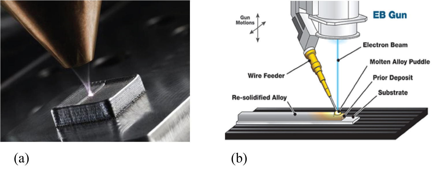
Figure 1: A schematic representation of the directed....
A schematic representation of the directed energy deposition-metal additive manufacturing process: a) The laser directed energy deposition process using powder feedstock material. Powder mixing is achieved in a separate chamber prior to injection; b) Electron Beam Additive Manufacturing (EBAM) Process. Wire Additive Manufacturing derives from the welding processes and corresponds to the melting of a metallic wire used as a deposit material.
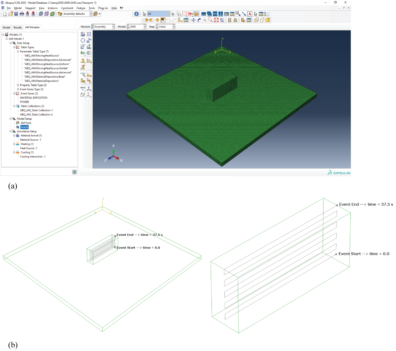
Figure 2: The ABAQUS AM Modeler plug-in: a) A screen capture....
The ABAQUS AM Modeler plug-in: a) A screen capture of the final DED part (total mesh, substrate + filler metal layers) and the AM modeler tab. Predefined types are shown here; b) A plot of the Select Event Series showing the path of the material deposition and heat input. Once the first layer is deposited, the energy source and the nozzle are moved upwards to deposit the next layer and the process is repeated until the complete 3D object is being fabricated. Event start time and event end time are also shown.
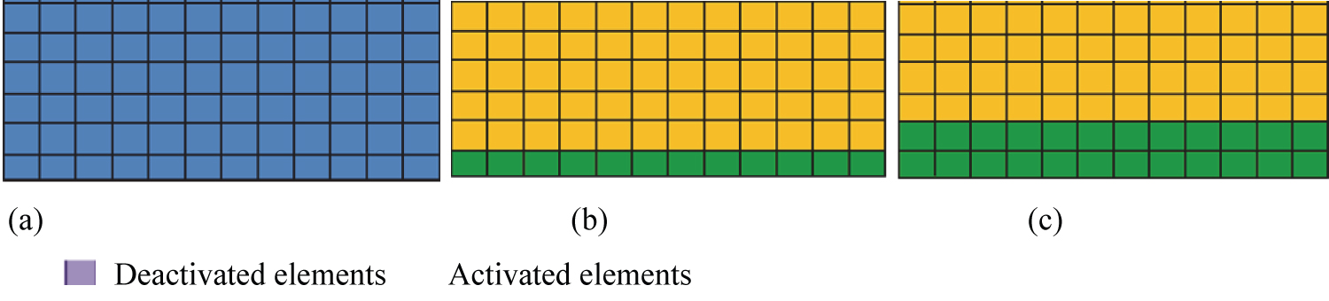
Figure 3: a) Filler metal mesh; b) Scan of 1st layer...
a) Filler metal mesh; b) Scan of 1st layer; c) Scan of 2nd layer.
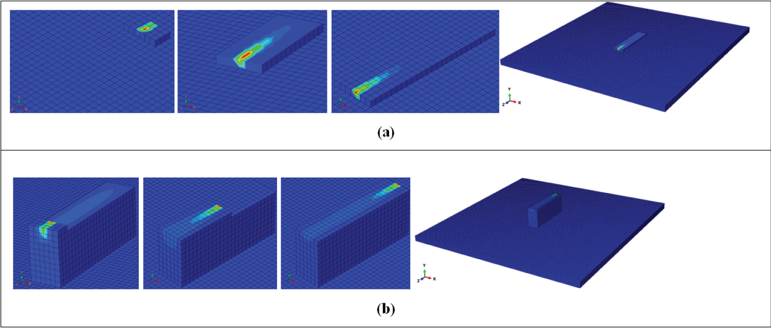
Figure 4: The layer built-up process in the thick....
The layer built-up process in the thick (12 mm bead width) wall component: a) The first layer formation; b) The tenth layer formation. Each completed layer is composed of 25 rows, and each row is composed of six DC3D8 elements of size 2 × 2 × 2 mm.The filler metal is laid row by row after each scan.
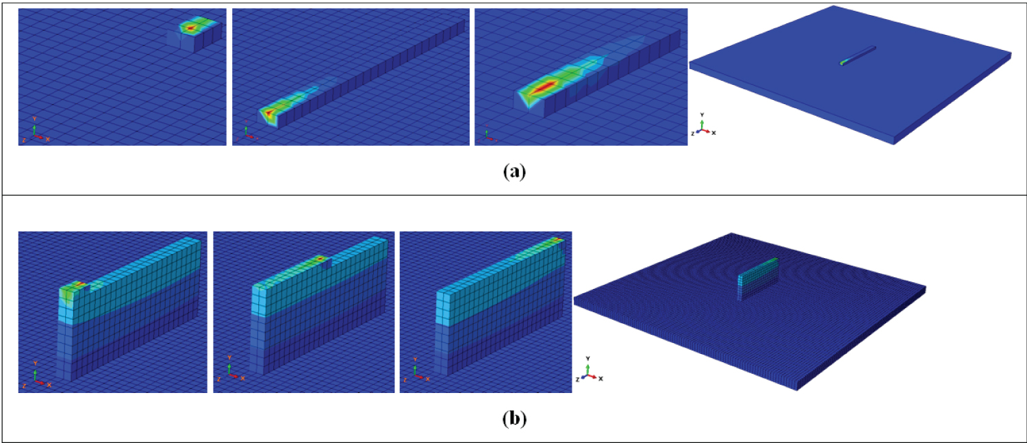
Figure 5: The layer built-up process in the thin....
The layer built-up process in the thin (4 mm bead width) wall component: a) The first layer formation; b) The tenth layer formation. Each completed layer is composed of 25 rows, and each row is composed of two DC3D8 elements of size 2 × 2 × 2 mm.The filler metal is laid row by row after each scan.
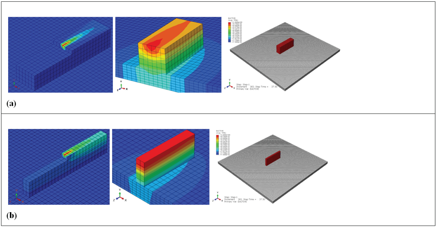
Figure 6: The automated element activation and....
The automated element activation and corresponding temperature contour in a X-Y cross section directly after printing: a) In a thick wall component; b) In a thin wall component.
References
- Marro A, Bandukwala T, Mak W (2016) Three-dimensional printing and medical imaging: A review of the methods and applications. Current Problems in Diagnostic Radiology 45: 2-9.
- Najmon JC, Raeisi S, Tovar A (2019) Review of additive manufacturing technologies and applications in the aerospace industry. Additive Manufacturing for the Aerospace Industry, 7-31.
- Hou M (2018) Overview of additive manufacturing process. Additive Manufacturing Materials, Processes, Quantifications and Applications, 1-38.
- Halada GP, Clayton CR (2018) The intersection of design, manufacturing, and surface engineering. Handbook of Environmental Degradation of Materials (Third Edition), 397-422.
- Ashish M, Nabeel A, Gopinath P, Vinogradov A (2019) Chapter 1 - 3D printing in medicine: Current challenges and potential applications. 3D Printing Technology in Nanomedicine, 1-22.
- Realistic Simulation with Abaqus Unified FEA. ABAQUS Unified FEA.
- Song X, Feih S, Zhai W, Sun CN, Li F, et al. (2020) Advances in additive manufacturing process simulation: Residual stresses and distortion predictions in complex metallic components. Materials and Design 193: 108779.
- Christine OH (2020) Use Abaqus to simulate additive manufacturing - printing a hip implant. Simuleon FEA Blog.
- Bonifaz EA, Palomeque JS (2020) A mechanical model in wire + Arc additive manufacturing process. Progress in Additive Manufacturing 5: 163-169.
Author Details
Edison A Bonifaz* and Andres Mena
Department of Mechanical Engineering, Universidad San Francisco de Quito, Casilla, Cumbayá, Ecuador
Corresponding author
Edison A Bonifaz, Department of Mechanical Engineering, Universidad San Francisco de Quito, Casilla Postal: 17-12-841, Cumbayá, Ecuador, Tel: 59322971700 ext. 1235
Accepted: August 05, 2021 | Published Online: August 07, 2021
Citation: Bonifaz EA, Mena A (2021) A Directed Energy Deposition Additive Manufacturing Process Simulated with ABAQUS AM Modeler. Int J Robot Eng 6:034.
Copyright: © 2021 Bonifaz EA, et al. This is an open-access article distributed under the terms of the Creative Commons Attribution License, which permits unrestricted use, distribution, and reproduction in any medium, provided the original author and source are credited.
Abstract
In this work, the ABAQUS AM modeler was employed to simulate a Directed Energy Deposition (DED) additive manufacturing process. The modeler provides an automated interface to prescribe the imposed tool path and process conditions. Though it may take some effort to understand how to use this element-birth technique approach, it is definitely worth the effort if you want to simulate additive manufacturing or similar processes. Two event series were utilized to prescribe material deposition and heat input. The automated element activation sequence was used to fabricate a thin (4 × 20 × 50 mm) and a thick (12 × 20 × 50 mm) wall component on a substrate. To approximate the 3D printing layer built up process, where filler metal is laid row by row after each scan, the component was fabricated with 10 successive layers (1 element through depth for each build layer), and each layer with 25 successive element rows. Once the first layer is deposited, the energy source and the nozzle are moved upwards to deposit the next layer and the process is repeated until the complete 3D object is being fabricated. It was found that to simulate problems where material and heat are added in a time and space dependent way, the use of the *ELEMENT PROGRESSIVE ACTIVATION option is much simpler than its counterpart *MODEL CHANGE. The AM Modeler helps to properly define the required data to approximate in a simple manner the 3D printing layer built up process. A laser path script was created in python language to allow for the path of the energy source and the nozzle. A right combination of printing parameters (feedstock and heat input) in the DED process has been established.
Keywords
Event series, ABAQUS AM modeler, Directed energy deposition, Heat input, Material deposition
Introduction
Additive Manufacturing (AM) process consists of creating 3-dimensional (3D) objects through successive deposition of materials in 2D layers. The additive manufacturing capabilities allow for material addition and sequential thermal mechanical analysis. 3D printers were first adopted by automobile and aerospace industry to create prototypes for testing before proceeding with mass production. In addition to prototyping, it is used to make a variety of finished products, including jewelry, batteries, and medical implants. When combined with medical imaging, 3D printing opens up new opportunities in the advancement of medicine [1]. In additive manufacturing, material is continuously added. Specific capabilities are therefore needed to efficiently set-up the simulation of problems that continuously change. Directed Energy Deposition (DED) is a group of AM processes that adds material alongside the heat input simultaneously. The heat input can either be a laser, electron beam, or plasma arc. DED technology works by melting material that is fed to a local site on the build layer, usually occurring within an inert gas atmosphere. While this can be used for nonmetal materials, it is predominately used with metals and metal alloys. DED processes build up the 3D part, layer by layer; however, the technology can be implemented in a multiaxial machine and provide 3D positioning [2]. This allows manufacturing of complex parts without the need of support structures. Due to increased versatility in orientation, DED technologies are ideal for component repair of turbine blades, engine combustion chambers, compressors, airfoils, and blisks [2].
Because of the technology's ability to inject metal powder directly into the heat source, often attached to a 4- or 5-axis arm, DED systems are not limited to 3D printing onto a flat substrate. Instead, it is possible to print metal onto curved surfaces, such as existing metal structures. For this reason, laser cladding is often used to repair damaged parts, particularly for the aerospace industry [3]. The added advantage of being able to direct the deposition to small areas or fine lines with a high degree of precision means that DED methods have found important applications in repair of failures (e.g., cracks) or defects, in providing a wear-resistant coating to a particular area, or and in protecting specific areas of an object from corrosion [4]. Directed energy deposition (DED) technologies allow the fabrication of 3D objects by utilizing focused energy source to melt the material deposited by a nozzle in the form of wire or powder (Figure 1). These techniques incorporate the characteristics of both power bed fusion and material extrusion techniques. However, different from the powder bed fusion techniques that melt the material pre-deposited on the substrate, these techniques melt the material as it is being deposited. Generally, a DED printer include a nozzle head that can move around a fixed object in multiple directions for depositing the material on the desired surfaces having geometry according to the CAD model and a high energy laser beam to direct the energy onto the desired surface to melt the material, that immediately gets hardened onto the platform [5]. DED techniques are unique in the manner, as these can be utilized to effectively repair or add to the preexisting part. Also known as rapid prototyping, this technology is changing the manufacturing industry, and its potential is beginning to be discovered in health care.
The ABAQUS AM Modeler
At the core of the additive manufacturing simulation capabilities of the new ABAQUS AM plug-in [6], is the toolpath - mesh intersection module. The newly introduced tool path - mesh intersection module automatically computes the relevant information required for the thermal and structural FE analysis, including the automated element activation, related heat input (as a function of time and space), and relevant thermal and structural boundary conditions for each given time step [7]. To interpret the event series information for material deposition and heat input, two built-in subroutine functions (UEPACTIVATIONVOL and UMDFLUX) are incorporated into the ABAQUS AM modeler. This is used to determine which elements have intersected with a path that is defined in time and space, for example the path of a tool. Without this, it is only possible to add elements at the start of a step, and the elements that are to be included need to be defined explicitly. The toolpath - mesh intersection module allows for a much looser coupling between the toolpath and the rest of the model. In this work, in the Define Parameter Table "ABQ_AM. Material Deposition. Bead" of the ABQ_AM_Table Collection-1, the "Bead Height" is related with both, the Y "Stack Direction" and the Below "Deposition Position", while the "Bead Width" is related with the X direction. To create the thick and the thin wall components using the same DED conditions, the "Bead Width" space was filled in with 12 mm for the thick and with 4 mm for the thin wall component. The use of this module is therefore very friendly to create wall components with different thicknesses by only changing the unique parameter "Bead Width". In addition, as the DED systems are not limited to 3D printing onto a flat substrate, to print metal onto curved surfaces, g codes can be converted to event series using replicator G. An available python script called generateEventSeries.py is mentioned in ref. [8].
In the DED process (mostly used for the deposition of metals), material deposition and heat are added at different points in space; and the outer surface, where heat loss occurs, changes over time. In this study, two event series containing the input data (material deposition and power) were included into the finite element analysis. A DED-AM model (total mesh, substrate + filler metal layers) is visible in the AM modeler tab (Figure 2a). It has different sections: Data Setup, Model Setup and Simulation Setup, of which the Data Setup is most extensive. Types for different data structures are mentioned, including the Parameter table, the Property table and the Event Series. A plot of the Select Event Series showing the path of the energy source and the nozzle are presented in Figure 2b.
The Layer Build-Up Process
In a previous work [9], to simulate the continuous wire addition in the WAAM process, the ABAQUS*MODEL CHANGE option was used. The layer build-up process was modeled by the following three steps: 1) The total mesh (substrate + filler metal layers) of the final DED part is created 2) All the elements within the filler metal layers are deactivated at the beginning of the simulation 3) The elements in the first filler metal layer are activated followed by the first arc scan. This process is repeated for the successive layers to approximate a real DED process, where filler metal is laid layer by layer after each scan. With *MODEL CHANGE all geometry that is to be included at any time in the model is defined from the start, and elements can be activated or deactivated during the analysis. However, it is not possible to change which elements are activated during the step, so gradual activation of different elements typically requires a lot of steps. For additive manufacturing, the amount of material that needs to be added is more extensive than for a typical welding analysis. This makes an analysis based on *MODEL CHANGE even more extensive and this strategy feels more like a workaround than that the software is meant to simulate the process of material addition [8]. The sequence of the layer build-up process is shown in Figure 3.
In this work, to activate the toolpath - mesh intersection module, the capabilities of *ELEMENT PROGRESSIVE ACTIVATION option were used. With this element-birth technique approach, we can define progressive element activation within a step based on a geometrical path and time instead of having to explicitly define when each (set of) element(s) is activated. The coupling between the toolpath and the rest of the model is therefore much looser. Because of this, refining the mesh or reducing the time increment size has a more gradual effect when using *ELEMENT PROGRESSIVE ACTIVATION compared to *MODEL CHANGE [8]. For example, if the time increment is reduced when using *MODEL CHANGE, then the same blocks of material will still be added at the same times, because material activation is explicitly defined between steps. If the time increment is reduced when using *ELEMENT PROGRESSIVE ACTIVATION, then the material will be added more gradually; Less elements will be activated per increment [6]. With the *ELEMENT PROGRESSIVE ACTIVATION option, the activated elements are nicely incorporated into the DED thermal analyses, where regions of heat loss tend to vary. On the other hand, in DED thermal analyses, the heat loss between the layer's surfaces and the surroundings depends on outer surface changes when elements are activated. This requires defining a lot of different surfaces, and different interactions to consider the changing surfaces. In the ABAQUS AM modeler, this capability has been incorporated to define convection and/or radiation and is under Cooling of the Simulation Setup interface.
Results
For initial validation studies of the new intersection modules, the Goldak-type approach with high mesh resolution on a build-plate was benchmarked. The AM modeler ensures the keywords that are relevant to additive manufacturing be included in the input files when the jobs are run. In a thermo-mechanical analysis, the thermal job is run first, followed by the mechanical job. The results presented in Figure 4 and Figure 5 show the layer formation during a DED additive manufacturing process. The elements are activated row by row according the event series information designed to deal with heat input, material deposition, and related "Bead Width". To approximate the 3D printing layer built up process, where filler metal is laid row by row after each scan, the component was fabricated with 10 successive layers Figure 6 (1 element through depth for each build layer), and each layer with 25 successive element rows.
Conclusions
1. It was found that to simulate problems where material and heat are added in a time and space dependent way, the use of the *ELEMENT PROGRESSIVE ACTIVATION option is much simpler than its counterpart *MODEL CHANGE.
2. The AM Modeler helps to properly define the required data to approximate in a simple manner the 3D printing layer built up process. A laser path script was created in python language to allow for the path of the energy source and the nozzle.
3. The toolpath - mesh intersection module is related with the created Event Series. That is, once the first layer is deposited, the energy source and the nozzle are moved upwards to deposit the next layer and the process is repeated until the complete 3D object is being fabricated.
4. A right combination of printing parameters (feedstock and heat input) in the DED process has been established.