
International Journal of Robotic Engineering
(ISSN: 2631-5106)
Volume 6, Issue 1
Research Article
DOI: 10.35840/2631-5106/4133

Article Formats
Deep Learning Empowered Far and Near Object Detection for Underwater Robots
Table of Content
Figures
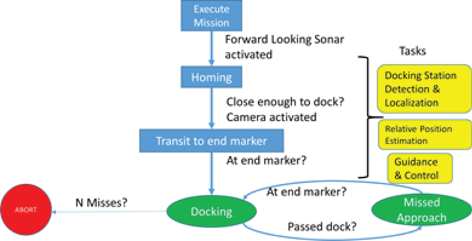
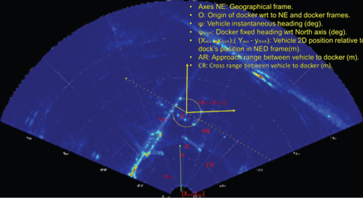
Figure 2: Information required by the.....
Information required by the AUV at any instant in time, include bearing angle, distance to go, target depth etc.,
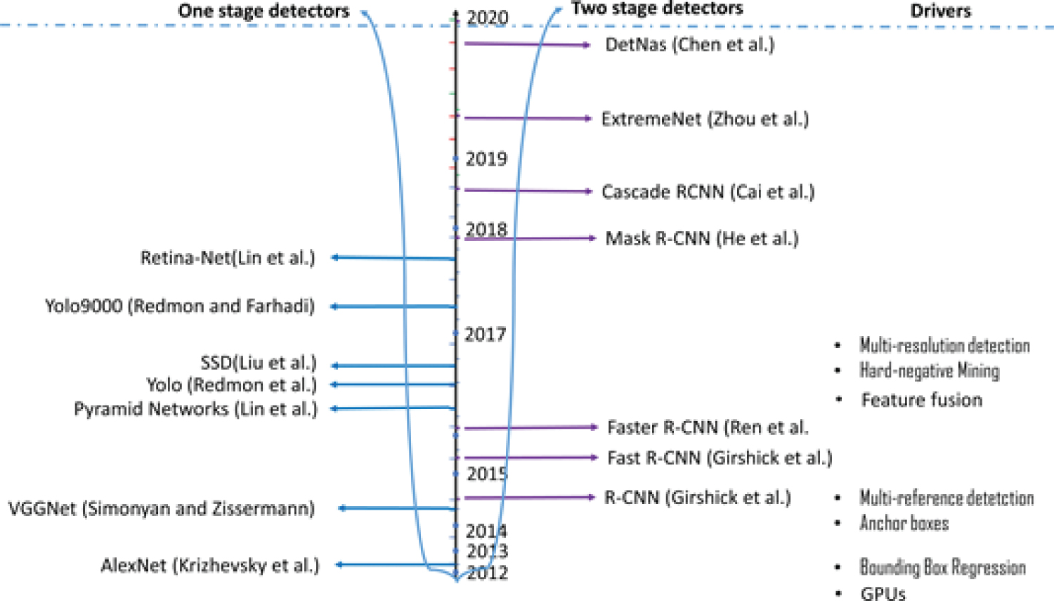
Figure 3: Major milestones in object....
Major milestones in object detection research based on CNN since 2012.
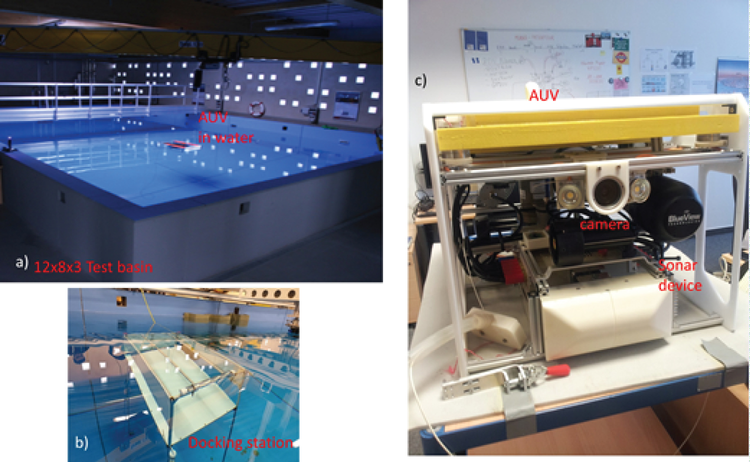
Figure 4: Overview of the system we used....
Overview of the system we used in the experiments: a) Test basin; b) Docking station; c) AUV with Sonar and Camera.
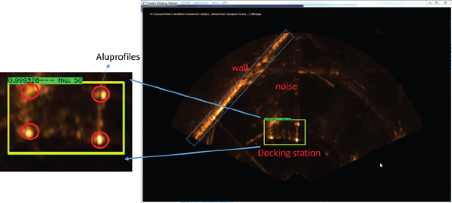
Figure 5: Signature of the docking station....
Signature of the docking station in sonar images, shows cross-sections of the aluminum profiles.
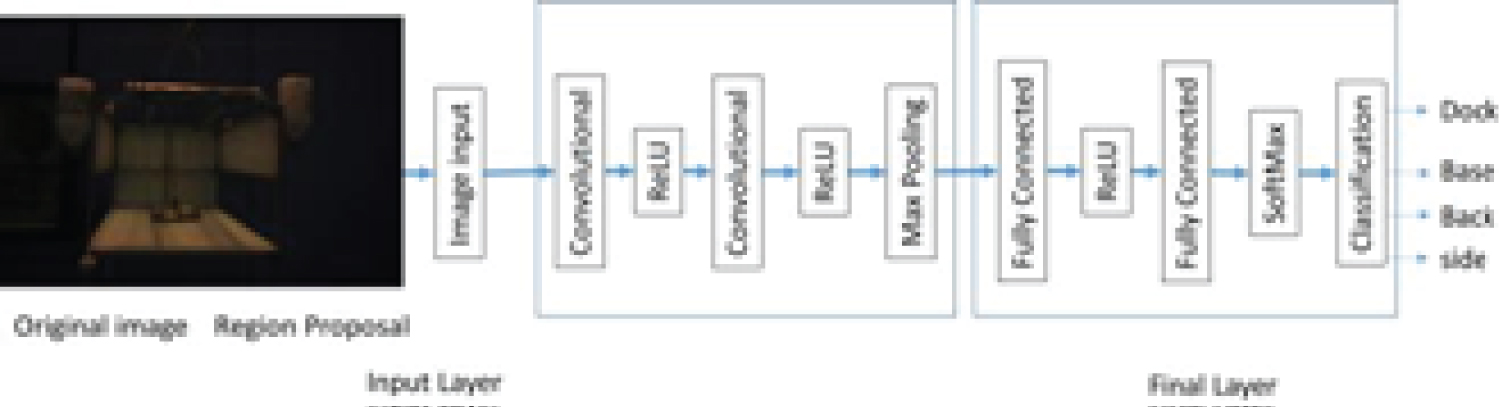
Figure 6: The structure of the network,....
The structure of the network, with convolutional and full connected layers, and final classification layer for the 4 classes, (dock, back, base and side).
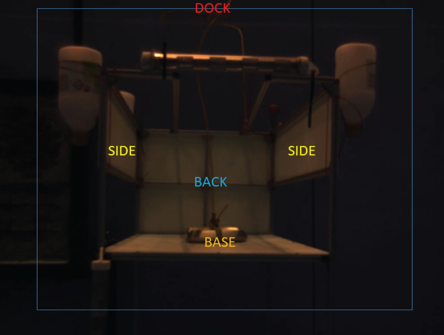
Figure 7: The important parts (sides,...
The important parts (sides, base, dock and back) of the docking station are the classes for detection.
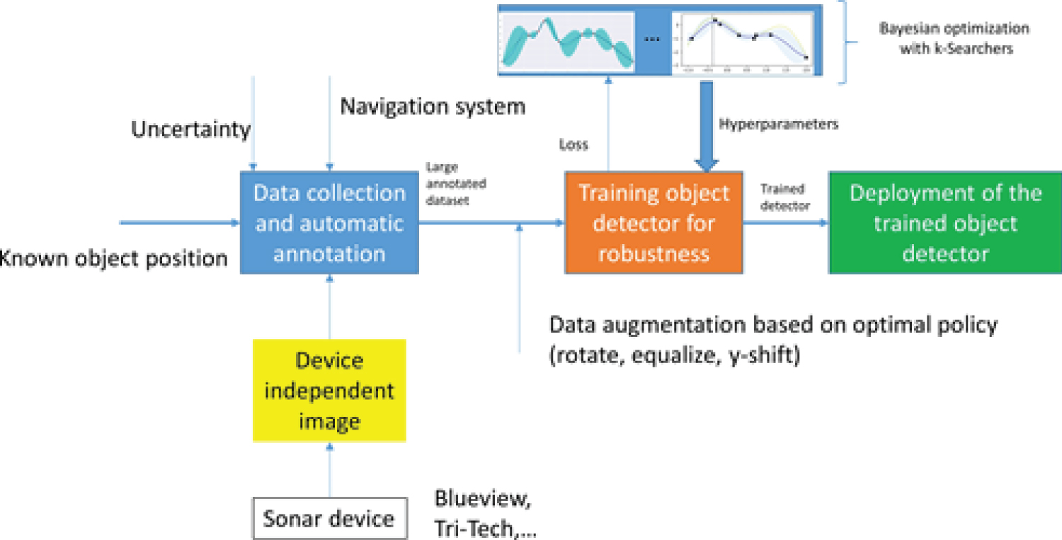
Figure 8: Pipeline for data collection...
Pipeline for data collection, detector training, hyperparameter search, data augmentation and deployment.
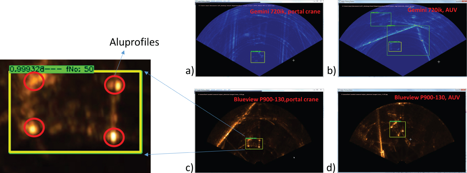
Figure 9: Results of the YOLO Network for...
Results of the YOLO Network for detecting the docking station in sonar images, robustness test for new sonar imaging devices: a) and b) Blueview P900; c) and: d) Gemini 720ik.
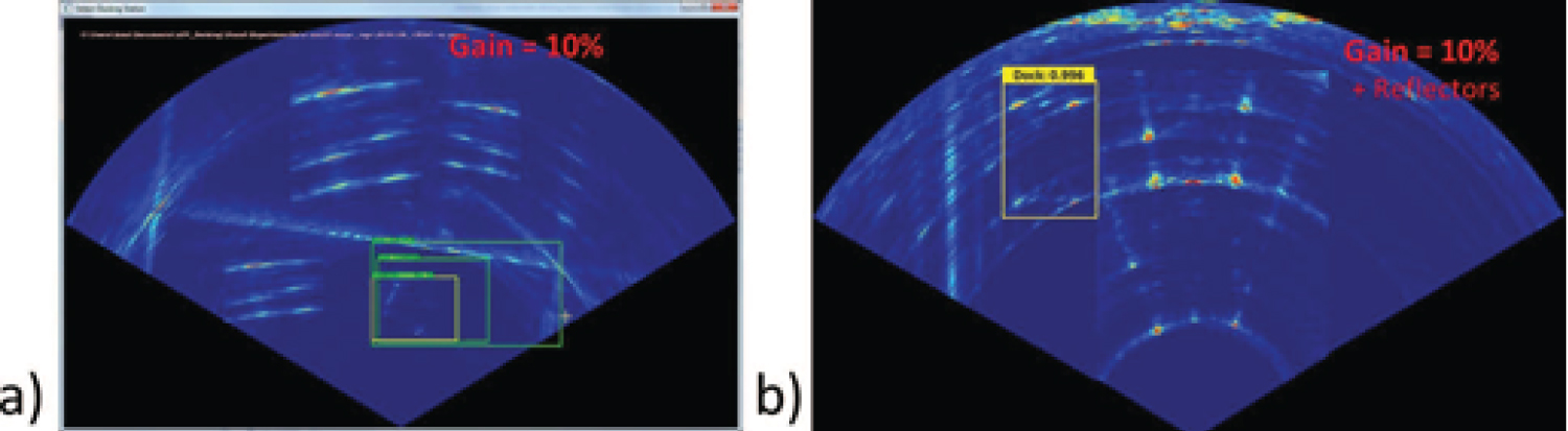
Figure 10: Results of the YOLO Network...
Results of the YOLO Network for detecting the docking station in noisy sonar images.
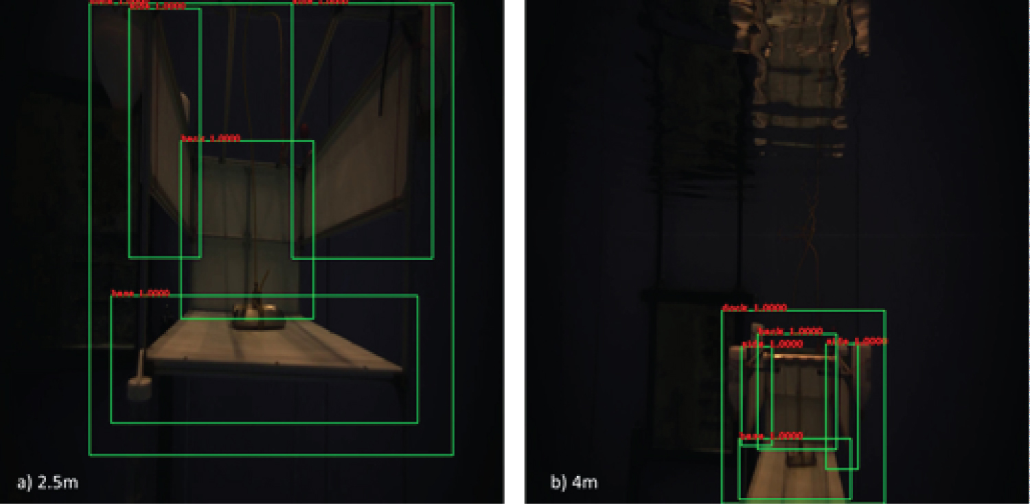
Figure 11: Results of the close range detecting...
Results of the close range detecting the docking station in optical images, the four classes (dock, back, base and side) can be detected very well from different positions, e.g., a) and b).
References
- Teo K, Goh B, Oh K (2014) Fuzzy docking guidance using augmented navigation system on an auv. IEEE Journal of Oceanic Engineering 40: 1-13.
- Li Y, Yanqing J, Cao J, Wang B, Li Y (2015) Auv docking experiments based on vision positioning using two cameras. Ocean Engineering 110: 163-173.
- Ying Y, Han J, Chen G, Wu J (2016) Development of an auv xuanwu-1 with docking function. IEEE, 1-7.
- Zhang T, Li D, Lin M, Wang T, Yang C (2016) Auv terminal docking experiments based on vision guidance. OCEANS 2016 MTS/IEEE Monterey, 1-5.
- Park J, Jun B, Lee P, Oh J (2009) Experiments on vision guided docking of an autonomous underwater vehicle using one camera. Ocean Engineering 36: 48-61.
- Maki T, Shiroku R, Sato Y, Matsuda T, Sakamaki T, et al. (2013) Docking method for hovering type auvs by acoustic and visual positioning. IEEE International Underwater Technology Symposium, 1-6.
- Krizhevsky A, Sutskever I, Hinton G (2012) Imagenet classification with deep convolutional neural networks. Neural Information Processing Systems 25.
- Chen Y, Yang T, Zhang X, Meng G, Xiao X, et al. (2019) Detnas: Backbone search for object detection.
- Liu W, Anguelov D, Erhan D, Szegedy C, Reed S, et al. (2016) Ssd: Single shot multibox detector. Lecture Notes in Computer Science, 2137.
- Redmon J, Farhadi A (2016) YOLO9000: Better, faster, stronger. arXiv: 1612.08242, 1-9.
- Qin H, Li X, Yang Z, Shang M (2015) When underwater imagery analysis meets deep learning: A solution at the age of big visual data. IEEE, 1-5.
- Cao X, Zhang X, Yu Y, Niu L (2016) Deep learning-based recognition of underwater target. IEEE International Conference on Digital Signal Processing, 89-93.
- Yahya MF, Arshad M (2017) Detection of markers using deep learning for docking of autonomous underwater vehicle. IEEE 2nd edn, International Conference on Automatic Control and Intelligent Systems (I2CACIS), 179-184.
- He K, Zhang X, Ren S, Sun J (2014) Spatial pyramid pooling in deep convolutional networks for visual recognition. IEEE Transactions on Pattern Analysis and Machine Intelligence, 37.
- Girshick R (2015) Fast R-CNN region-based convolutional neural network. Proceedings of the 2015 IEEE international conference on computer vision (ICCV), 1440-1448.
- Uijlings J, Sande K, Gevers T, Smeulders A (2013) Selective search for object recognition. International Journal of Computer Vision 104: 154-171.
- Ren S, He K, Girshick R, Sun J (2016) Faster R-CNN: Towards real-time object detection with region proposal networks. arXiv: 1506.01497, 1-10.
- Dai J, Li Y, He K, Sun J (2016) R-FCN: Object detection via region-based fully convolutional networks. In: Proceedings of the 2016 conference on advances in neural information processing systems (NIPS), 379-387.
- He K, Zhang X, Ren S, Sun J (2016) Deep residual learning for image recognition. In: Proceedings of the IEEE computer society conference on computer vision and pattern recognition (CVPR 2016), 770-778.
- Alexe B, Deselaers T, Ferrari V (2012) Measuring the objectness of image windows. IEEE Transactions on Pattern Analysis and Machine Intelligence 34: 2189-2202.
- Schweighofer G, Pinz A (2006) Robust pose estimation from a planar target. IEEE Trans Pattern Anal Mach Intell 28: 2024-2030.
- Lu CP, Hager GD, Mjolsness E (2000) Fast and globally convergent pose estimation from video images. Patt Anal Mach Intell, IEEE Trans on Pattern Analysis and Machine Intelligence 22: 610-622.
- Everingham M, Van Gool L, Williams C, Winn J, Zisserman A (2010) The pascal visual object classes (voc) challenge. International Journal of Computer Vision 88: 303-338.
- Lin TY, Maire M, Belongie S, Hays J, Perona P, et al. (2014) Microsoft COCO: Common objects in context. In: Fleet D, Pajdla T, Schiele B, Tuytelaars T, Computer Vision - ECCV 2014, Lecture Notes in Computer Science, Springer, Cham, 8693.
- Shelhamer E, Long J, Darrell T (2016) Fully convolutional networks for semantic segmentation. IEEE Transactions on Pattern Analysis and Machine Intelligence 39: 1-1.
- Nair V, Hinton GE (2010) Rectified linear units improve restricted boltzmann machines. Proceedings of the 27th International Conference on Machine Learning, Haifa, 807-814.
- Zhou Y, Chellappa R (1988) Computation of optical flow using a neural network. IEEE 1988 International Conference on Neural Networks 2: 71-78.
- Blaschko M, Lampert CH (2012) Guest editorial: Special issue on structured prediction and inference. International Journal of Computer Vision 99: 257-258.
Author Details
Divas Karimanzira*, Torsten Pfützenreuter and Helge Renkewitz
Fraunhofer IOSB Am Vogelherd 90, Germany
Corresponding author
Divas Karimanzira, Fraunhofer IOSB Am Vogelherd 90, 98693 Ilmenau, Germany.
Accepted: August 02, 2021 | Published Online: August 04, 2021
Citation: Karimanzira D, Pfützenreuter T, Renkewitz H (2021) Deep Learning Empowered Far and Near Object Detection for Underwater Robots. Int J Robot Eng 6:033.
Copyright: © 2021 Karimanzira D, et al. This is an open-access article distributed under the terms of the Creative Commons Attribution License, which permits unrestricted use, distribution, and reproduction in any medium, provided the original author and source are credited.
Abstract
Docking capabilities are required for long operation of an Autonomous Underwater Vehicle (AUV) due to limited battery and data storage capacity. Docking is composed of four main processes, i.e. homing, plug-in, release and drive-out. The homing part requires detection and localization of the docking station, guidance and control to reach the docking station. Hence, in this paper, we focus on the process of detection and localization. The AUV is assumed to use two sensors for perception of the environment, i.e. an imaging sonar and a monocular camera which is used in close range navigation. Deep learning (DeepL) methods are well-known for good detection and localization. Therefore, in this paper, two DeepL networks will be designed. The first one is for detecting the target object in a sonar image at far range and the other one is for detection of the docking station in the close range using data from an optical camera image. The results from experimental studies in a test basin with an AUV show that the proposed system is able to locate and classify the docking station in both optical and sonar images with detection rate of 94.3% and 80%, respectively.
Keywords
Sonar images, Underwater robot, Deep learning, Object detection
Introduction
Nowadays, Autonomous Underwater Vehicles (AUV) are able to perform tasks such as underwater exploration, an inspection of underwater structures, search for black-boxes and wreckages, and underwater manipulation. Much to the advancement of AUV, due to the limited nature of battery energy storage capacities and onboard data storage capacities, the AUV needs to be continuously deployed and retrieved during a mission. This is tiresome and very expensive. One possibility to overcome the power and data storage limitation is to use an underwater docking station as a filling station for the AUV to recharge its battery and free the data warehouse. To fulfill docking capabilities the AUV requires some sensors for environmental perception. Despite the fact that acoustic sensors (sonar) are the first choice for many underwater applications, vision is more appropriate in the proximal region of the docking station. There have been several developments in vision-based underwater docking Teo, et al. [1]; Li, et al. [2]; Ying, et al. [3]; Zhang, et al. [4]; Park, et al. [5]. For example, in Park, et al. [5], a cruising AUV is used for docking using a single camera attached to its nose. The docking station is of a funnel-shaped to accommodate the torpedo-shaped AUV. In Maki, et al., [6] a hovering type AUV docks into a rectangular-shaped docking station Maki, et al. [6]. This vehicle also uses as in Park, et al., a camera to acquire image as a source of information to control its homing trajectory when docking Park, et al. [5].
Besides the sensors, algorithms for detection, localization, and classification of the target object placed at the docking station parts, such as the sides, base, back etc. for identification is of great importance. Mostly, sealed light bulbs or light-emitting diodes placed either at the entrance or in the docking station are used as identification objects. These devices as identification objects require extensive image preprocessing to discriminate the light sources with the light of the environment due to issues that can arise such as reflection, scattering, loss of target, and occurrence of noise when the image is processed. Li, et al. [2] and Park, et al. [5] reported docking failure in cases of target object occlusion or loss of features of target object or disorientation of the view of the features from the camera. This makes the traditional image processing techniques used in Li, et al. [2] and Park, et al. [5] not robust enough to process the image for underwater docking.
In this paper, two networks will be designed. The first one for detecting the target object in the sonar image at a far range is based on the YOLO concept and the other one is a region-based convolutional neural network (CNN) architecture for detection of the docking station in the close range using data from an optical camera. The experimental study includes real-time processing of locating and classifying the features of a docking station. Further, how robust the detection of the docking station is when there are changes in image intensity, disturbances, e.g., due to reflections caused by nearby objects and view of the target is assessed.
Requirements of a guidance system on the detection and localization
The process of homing an AUV from arbitrary positions is shown in Figure 1. The homing process begins with the mission execution and activating the forward looking sonar device. When the docking station is detected by the detection algorithm using the sonar, homing start and at each time instant the information in Figure 2 are calculated by the detection system for the guidance and control system and when in close range the camera is activated to give 3D information. Instead of using markers, we detect parts of the docking station such as the back, sides and base as our markers. In order for an AUV-Homing to be successful, the AUV must always determine at least the Azimuth and depth of the target as shown in Figure 2. For example, a guidance system based on Line of sight (LOS) and Cross Track Error (XTE) control requires the knowledge of the relative position and orientation of the AUV to the docking station. Because vehicle orientation, bearing and distance to the docking stations is important near the docking station, the detection and localization system will require high update rates.
Deep neural networks for object detection
Based on human vision and how humans classify objects in an image, deep learning provides an optimal architecture for image recognition and pattern detection without the need to analyze the features in in the image. In most cases, deep learning is implemented as a multi-layered neural network with several layers.
Over the past years, significant amount of work has been carried out towards deep learning based object detection, from the work of Krizhevsky published in 2012 - The Alexnet Krizhevsky, et al. [7] to DetNAS Chen, et al. [8] as shown in Figure 3. A pivot point in the timeline of object detection was the development of the Deep Convolutional Neural Networks (CNNs) approach, which was enabled by several drivers such as the introduction of hardware innovations i.e., GPUs and algorithms e.g., bounding box regression and feature fusion.
Basically, there are two types of models which are being used for object detection mainly in optical images. One stage detector, which directly predicts the bounding boxes of an object in an image in one shot e.g., the Single Shot Detector Model (SSD) Liu, et al. [9] and Yolo Redmon and Farhadi [10] and two stage detectors, which include objectness region proposal in the first stage. The R-CNN and family are typical two stage detectors with decision refinement in the second stage. Unfortunately, a compromise have to be made between the application of the two models, because the one stage detectors are faster than two stage ones but subject to low accuracy in cases where high Intersection over Union (IoU) is required.
The State-of-the-art object detection networks depend on region proposal algorithms to hypothesize object locations. Girshick, et al. 2017 proposed to use a region-based convolutional neural network (R-CNN) for localization and classification of objects in an image. Deep learning has also been used to analyze big visual underwater data Qin, et al. [11] and to recognize underwater targets Cao, et al. [12]. A promising method based on deep learning is used in Yahya and Arshad [13] for marker detection placed on an underwater target object. Some advancement by He, et al. [14]; Girshick [15] have reduced the computation time of the R-CNN drastically, exposing region proposal computation as a bottleneck. This can be explained as in the following.
The R-CNN follows three main steps, with 1) The generation of proposals for the regions for the bounding boxes, 2) Classification and 3) Running the boxes found through a linear regression model to tighten the coordinates. Therefore, three models have to be trained separately which is quite hard. R-CNN generates these region proposals, using a method of Selective Searching Girshick [15]; Uijlings, et al. [16]. This method of selective search applies windows of various sizes to the image, tries to link adjacent pixels by features such as texture, or intensity to identify the potential objects. This makes the R-CNN quite slow. In 2015, Ross Girshick solved the two problems, leading to the Fast R-CNN. The Fast R-CNN uses one network for the three procedures. In Fast R-CNN, a softmax layer runs in parallel with a linear regression layer on top of the CNN to output a classification and bounding box coordinates, respectively. In mid 2015, Microsoft Researchers introduced the Faster R-CNN, by adding a Fully Convolutional Network (Region Proposal Network) over the features of the CNN Ren, et al. [17]. This made the region proposal step almost cost free. Instead of locating just bounding boxes, but exact pixels of potential object (image segmentation problem), Researchers at Facebook AI introduced a further development, the Mask R-CNN by adding a Fully Convolutional Network on top of a CNN based feature map that says whether or not a given pixel is part of an object.
However, a problem remains that all these detectors which are region-based use subnetwork per region several times, which is computationally expensive. Therefore, the authors in Dai, et al. [18] proposed a region-based R-FCN detector, which is fully convolutional networks that share almost all the necessary computation over the entire image. The architecture is now adopted for object detection in most of the fully convolutional image classification backbones, such as the Residual Networks (ResNets) He, et al. [19].
Another CNN-based approach for object detection is YOLO Redmon and Farhadi [10], which is an end-to-end detection and classification system. The image is divided into a grid which is 7 × 7, and ground truth objects are assigned to the grid cells. Each of the cells predicts a bounding box, objectness Alexe, et al., [20] and a probability distribution over classes. A threshold can be set for the objectness thresholded to produce detections with class information.
This YOLO detection model performs less than the R-CNNs but it is several times faster. For each of the detection blocks of the YOLO Net, there are 3 branches. The first branch is for cropping the boxes of the various aspect ratios. The second one is used for predicting the confidence scores for each bounding box, and finally, the positions of all the generated boxes are fine adjusted by the third one.
Methods
The method proposed in this paper is determined by the perception system which is composed of an acoustic imaging device and a camera and the target hardware, which is a NVIDIA Jetson TX2 Board. The system shown in Figure 4 is composed of an AUV with a forward looking sonar device, optical camera, a NVIDIA Jetson TX2 Board for deployment of the detectors, test basin and the docking station to be identified. The docking station is made out of aluminum profiles and gives a signature in sonar images as shown in Figure 5. This signature is what need to be found by the deep learning algorithms.
Even though acoustic imaging devices suffer from low resolution, speckle and other defects, they got no problem with turbidity and can take images of object very far away. Unfortunately, the acoustic imaging devices only give 2D representation of the objects as cross section which makes it difficult to use the information for manoveuring into the dock when at close range where the AUV need to know the 3D relative position of the dock. Here comes the camera into play. Even though optical cameras also do give 3D information directly, there are many feasible techniques for 3D reconstruction from 2D images [21,22].
Based on this, a two detector system is designed for the far range and close range.
The first detector is based on the sonar data and the YOLO architecture. This detector has less requirement on the IoU. But high requirements on position update speed, because the AUV is allowed to travel fast to come as quick as possible to the proximity of the docking station. The YOLO architecture is used for this purpose because it is faster and when the docking station is at a faraway position, let us say over 30 m, the exact position (position accuracy) is not that import. The second detector is based on the vision data from the camera and underlies the procedure for region proposal convolutional neural network (R-CNN). Although methods that do not rely on region proposal do exist, e.g., Liu, et al. [9]; Redmon and Farhadi [10], region-based systems still possess leading accuracy on several benchmarks Everingham, et al. [23]; Lin, et al. [24]; Shelhamer, et al. [25].
Image recognition using Deep Learning methods is known to require vast amounts of manually labeled data, we apply transfer learning of pre-trained network which uses generic features learnt with data from a different domain. In underwater object detection with sonar, it is very difficult and expensive to collect a lot of data, therefore the datasets are usually small, which makes such data-efficient learning methods interesting for us to explore for sonar object detection with limited number of training data. All the two detectors are based on the TensorFlow API. The TensorFlow API includes several model types in the model zoo, which can be utilized using transfer learning for example. For the two detectors we train to minimize the error between ground truth bounding boxes and the predicted bounding boxes for each grid. Therefore, the loss function can be expressed as in Liu, et al. [9] as follows:
penalizes the discrepancy between the predicted bounding box and their ground truth for each grid cell. is the penalty factor for the confidence score for the grid cells containing docking stations. is the penalty factor for the confidence score for the grid cells without docking stations.
Further, as shown in Liu, et al., in their experiment that the conditional probability of Classc to Objectness, Pi (Classc Objectness) used in YOLO introduced instability in the learning process when applied to a system with one prediction class and a small datatset, therefore in this work we modified the loss function used in YOLO by using Pr (Docking station) instead of an objectness and a conditional probability.
The procedure starts with collecting data for training through experiments in the test basin, labeling the data, creating the YOLO network and the R-CNN architecture, and trains the networks with the prepared data. After training the YOLO Net and the R-CNN are implemented on a NVIDIA Jetson TX Board, tested and used online during the docking procedure to enhance navigation into the dock of the AUV.
Long-range detection
At a far distance, the guidance and control algorithm need to know only the bearing of the docking station from the AUV position. We only need to detection one class, i.e., the docking station with the signature shown in Figure 2. In our case, we require a high-speed model that can work in real-time. Therefore, the YOLO detection network was chosen for the long-range detector. The YOLO, as the name suggests, does the determination of all bounding box probabilities at once, which makes it very fast. However, the speed gain is realizable at the cost of the network accuracy. The detector has got only one class to predict the docking station. After configuring the YOLO Network, the model was retrained with our own data collected in the test basin. Training the entire YOLO Net model on our own data from scratch would need thousands of training images, multiple GPUs, and roughly a week of training time.
Therefore, we applied the much easier solution, whereby we took an already-trained network on a large data set and clipped off its last layer, which has the classes from the trained model and replaces it with our own classes. By doing this, we could use all the feature detectors trained in the previous model and use these features to try to detect our new classes.
Close range detection
The close range detection of the docking station is performed using a convolutional network based on the R-CNN architecture. The network structure is illustrated in Figure 6 and will be described in the following.
The CNN is composed of 10 layers of which the first layer is the input layer of size 32 × 32 × 3 (Kernel 32 × 32 × 3 for the RGB). We apply a 3-by-3 filter size to scan the 32 × 32 × 3 size image, which makes a requirement of a total of 32 filters. We set the stride to two for the convolutional layers and we use a padding of value 1 to take the edges of the images into account.
Furthermore, four layers are added that comprise of a 2D convolutional layer, with rectified linear unit-(relu) layer activation Nair and Hinton (2010) [26], another convolutional 2D layer also with rectified linear unit-(relu) layer activation, and max pooling layer Zhou and Chellappa (1988) [27] in that order. The same number of filters and filter size as the input layer are applied to the 2D convolutional layers with padding value of 1. Obviously, we have to include the relu activation functions to introduce nonlinearity into the CNN. This also gives the CNN the ability to alleviate the disappearing gradient problem in the following lower layers and make the CNN train faster. The max pooling layer is responsible for the down sampling which reduces the computing costs and it controls the generalization ability of the CNN by avoiding overfitting.
Furthermore, five layers which consist of a fully connected layer (FC), rectified linear unit layer, another FC layer, soft max layer, and a layer for classification are added to the CNN after the max pooling layer. The size of the FC layer following the max pooling layer is 64 and the output classes determines the size of the other FC layer 2. The FC layer in combination with soft max and classification layers will unite the features in the image to a particular class of an object based on correlation. The R-CNN includes a final layer of the CNN in the form of a Support Vector Machine (SVM) that is for classification and determines the class of an object. There 4 classes, which include the "dock", "base", "back" and "side".
The R-CNN detection framework has difficulties in localization and we address this with two ideas. Firstly, we applied a fine search based on Bayesian optimization to expand the initial set of bounding boxes with new one with scores that are likely to be higher. Secondly, we used a structured SVM objective in the classification step that took both classification and localization (overlap with the ground truth) into account.
Fine search (FGS) Problem formulation: Suppose the function f(x,y) denote an object detection score for a given image x for the bounding box coordinates y = (a1,b1,a2,b2)Y. Then the goal is to find the local maximum value of f(x,y) subject to of a new image x. Let y1,...,yN be the solution set of bounding boxes.
Utilizing the Bayesian framework for optimization to solve the problem, it is assumed that f = f(x,y) is drawn from a probalistic model , where and fj = f (x, yj). Now the aim is to find another solution yN+1 that maximizes the probability of improving the detection score fN+1, where the probability is an acquisition function a(yN+1|DN) (e.g., expected improvement). Specifically, a Gaussian process (GP) is used to define p(x) and p(yN+1, xN+1, DN+1) can be determined by GP regression. The algorithm proceeds recursively as follows: A new solution yN+t is sampled from DN+t-1, and the set DN+t = DN+t-1 yN+t updated to draw a new solution yN+t+1 with an updated observation.
Training the R-CNN with structured loss which penalizes both the classification and localization errors assume the top layer of the R-CNN is a classifier f (x, y; w) = wT φ(x, y), where φ(x, y) denotes the CNN features from the preceding layer. In contrast to the solution in Blaschko and Lampert, [28] we use the results of the selective search and we restrict the output space to these regions.
Data preparation for the two detectors
In an experimental setup, where the docking station is mounted in a test basin, an AUV equipped with a Gemini 720 ik or a Blueview 900 forward looking sonar device and a camera is driven around the docking station collecting acoustic and optical images. The images consist of 3 channels in RGB format. For each device, images were manually annotated to form three datasets, one for training, the second one for validation and the last one for testing the network. The dataset for training the YOLO network for the long range detection using the forward looking sonar comprises a total of 627 acoustic frames with or without a docking station plus 800 sonar images with added noise or taken where the environment included foreign sonar reflectors to increase reverberations and disturbances. Half of the 1427 images were collected using the Gemini und the rest with the Blueview device (the two devices have different image quality). This is important so that at the end the final detector is sonar device type independent. The 800 images were important for evaluating the robustness of the detectors against disturbances. From the 1427 images, 50% were used for training, 30% for validation during training and the rest for testing. A hinged loss (a sum of Classification and Localization losses) was used for training with the latter calculated only for boxes with the same class label as the ground truth.
For the close range, 1239 optical images were selected according to their class inclusion. We made sure that all the classes (sides, base, dock and back parts, see Figure 7) were acquired almost equally to reduce bias in training. In the 1239 optical images dataset, there were 1200 dock class, 1239 base class, 1600 side class and 1239 back class labels. Again from the 1239, 50% images were used for training, 30% for validation during training for early stopping and 20% for testing.
In this experimental set up, the AUV was moved around the test basin so that the sizes of the collected images vary from one image to another in orientation and position of the docking station. After data collection, firstly for the two detectors, 200 frames of each dataset collected went through a manual labeling process.
Manual labeling of images is a very cumbersome job and quite expensive, especially for the short range detector with 4 classes, therefore, we developed the following strategy for collecting and automatic labeling of more data. Firstly, using the small dataset of about 200 images and using transfer learning, we saw that the simple detector was quite good. So we used it in inference phase for the rest of the dataset or while driving the AUV in the test basin to detect the docking station while using the detected bounding boxes for creating the annotation file. For sure not all the annotation were perfect, therefore another manual step was required for an expert to check the results and correct the few labels which were wrong. At the end we had a large annotated dataset, which we then used to further train the detectors. The pipeline is described in Figure 8. During training data was also increased using augmentation like rotation, y shift etc. with optimal policy.
Results and Discussion
During training, we monitored the trend of the loss function for training and validation, and the accuracy of the two detectors as indicators of the network’s training progress. To evaluate the performance of the final trained models for detecting the docking station in the sonar images, the network was tested on the testing subset consisting of 546 images. The overall mAP Everingham, et al. [23] was determined. The mAP is the mean AP across all classes being considered in the evaluation. For the long range detector, we got one class, therefore mAP = AP. Since this is a single class problem, the area under the PR curve for docking station detection is equivalent to AP. Only detections above a given threshold will be considered and put in comparison with the ground truth bounding boxes. In our case, we set the minimum Intersection over Union (IoU) between the ground truth bounding box and the predictions to 0.5. Obviously we expected one docking station so several detections of the docking station in an image were considered false. We define the precision for a single detection run and the recall as the number of true positives (TP) over the total number of predictions and the number of TPs over the number of true instances of the docking station, respectively. During training, the network stopped improving before the maximum number of epochs was reached.
After training via fine tuning the YOLO network for the detector of the docking station in sonar images with pre-trained weight initialized across every layer, the network achieves a AP value of 87.3%. Through visualizing by plotting the detection results, we can see that the YOLO network produces reasonable detections with high confidence and accurate bounding boxes. Example detections are shown in Figure 9a to Figure 9d.
The long-range detector is not designed to be used for detecting docking stations in forward looking sonars only, but also for other sonars like SAS or side scan sonars and furthermore, the system should be usable independent of the capturing device. Even through the long-range detector was trained with data from a Tritek Gemini 720ik forward looking sonar (Figure 9a and Figure 9b.), it was important to test the robustness of the detector to changes in the capturing device. Therefore, a Blueview 900 sonar device was mounted on the AUV and used for online detection of the docking station. The results are shown in Figure 9c and Figure 9d.
Furthermore, noise can be induced by other factors such as the proximity of the docking station to other objects, the phenomenon of the sonar and the vibrations caused by the AUV propellers and movements. The gain can also amplify the noise in the images even though it is always chosen carefully. The results of such robustness test to noisy sonar images are shown in Figure 10a and Figure 10b.
The performance of the detection and localization system for the close range using R-CNN is measured using the detection rate, i.e., the total number of detections compared to the actual all docking station position in all images and the localization accuracy, i.e., the correct location detection of the docking station compared to its actual location in an image for all 674 test images. The results are shown in Figure 11 and Table 1. The table shows that the detection rate is quite high for all images with docking data achieved above 80% detection rate. Further, the system is able to localize the docking station on all data sets quite accurately with the minimum being 94.3%. Extremely blurred frames can make detection difficult, when it becomes impossible to extract a good target boundary with the edge detector.
Conclusions
A detection system of an underwater docking station has been presented. It is based on Deep learning neural networks and composed of two detectors for long and close range detection. The Yolo network architecture is used for the long range detection in sonar images. It presents an object detection model using a single deep neural network combining regional proposals and feature extraction. The neural network is trained to learn the features of the docking station in the acoustic image. It can be concluded that the proposed system is able to classify the docking station and localize it. Using an RCN the acoustic image is segmented into regions of interest. After this procedure, the detected region of interest are labeled i.e., annotated manually by the user for training. A much easier solution for training the Yolo was used. A model already trained on a large data set was used, whereby the last layer was clipped off, which has the classes from the trained model, and replaced with on own classes. In the close range an R-CNN structure is applied to learn and detect markers placed on the docking station. Its region proposal is improved using FGS and Bayesian Optimization. Very good results were obtained for both short and long range detection in optical and sonar images, respectively. Future work include introducing partial occlusions, blurring furthermore of the images to further test the robustness of the system.
Declaration of Conflicting Interests
The authors declare no conflict of interest.
Funding
This research received no external funding.
Supplemental Material
There are no supplemental materials to this paper.
Acknowledgements
Thanks to Fraunhofer and Kraken Robotics Inc for sponsoring the work in the paper. http://www.fhg.de; https:// krakenrobotics.com. Thanks to the colleagues at Application Center Ilmenau for data collection.