International Journal of Robotic Engineering
(ISSN: 2631-5106)
Volume 3, Issue 2
Review Article
DOI: 10.35840/2631-5106/4112

Article Formats
Gyroscope for Robot to Sense the Balance
Table of Content
Figures


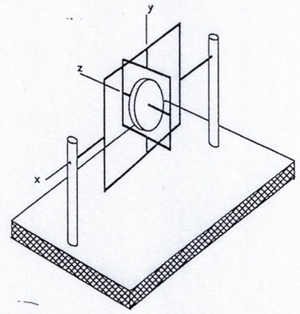
Figure 3: Two-degree-of-freedom gyro...
Two-degree-of-freedom gyro (Rotation about x axis restricted).

References
- Vallery H, Juhn-Yin Li D (2014) Gyroscopic-assisted device to control balance. Khalifa University of Science, Technology & Research.
- Lee H, Choi K, Kim D, Bang S (2010) Apparatus and method for correcting bias of gyroscope mounted on mobile robot.
- Ying SJ (1997) Advanced dynamics. AIAA Education Series.
Author Details
Shuh Jing Ying*, Rajiv Dubey and Stephen Sundarrao
Department of Mechanical Engineering, University of South Florida, USA
Corresponding author
Shuh Jing Ying, Professor Emeritus, Department of Mechanical Engineering, University of South Florida, Tampa, Florida, USA.
Accepted: December 27, 2018 | Published Online: December 29, 2018
Citation: Ying SJ, Dubey R, Sundarrao S (2018) Gyroscope for Robot to Sense the Balance. Int J Robot Eng 3:012.
Copyright: © 2018 Ying SJ, et al. This is an open-access article distributed under the terms of the Creative Commons Attribution License, which permits unrestricted use, distribution, and reproduction in any medium, provided the original author and source are credited.
Abstract
Many papers are using gyroscope in their titles but only a few are actually related to the balance of robot, some are reviewed in the paper. To understand the motion of gyroscope, fundamental theory is reviewed and some cases are quoted here as examples. The spinning axis will oscillate because of the rotation of Earth. It is certainly not expected. The device proposed here has its spinning axis perpendicular to the surface of Earth and it is served as a vestibular system in the human ears for humanoid robot. Condensers are used as sensors to detect the deviation from its neutral position. Oscillation circuit will be built and frequency detector will be used. The detected signal will be sent to the computer in the robot to restore it to a proper position.
Introduction
In human body there is a vestibular system in ears to sense the balance of body in proper position. This system detects the position of body and sends the signal to the brain to do the corrections. We feel that a similar system must be established in a humanoid robot to sense the balance of the robot. In case if the robot is out of balance the system will send a signal to the computer serving as a brain for the robot to make any necessary corrections to the position of robot so that the robot will be always in a proper balanced position without fall. We think that gyroscope is a proper device for this purpose. It is well known that gyroscope is used in a large airplane as an autopilot to keep the airplane in straight flight. Fundamental principle of gyroscope and its applications will be given in this paper. Actual mechanism will be also proposed in some detail so that this paper will connect theory to practical application.
Many papers are using gyroscope in their titles, but actually they are not for the motion of a robot. A paper entitled 'Gyroscopic-Assisted Device to Control Balance' by the Department of Technology & Research, Khalifa University of Science, Abu Dhabi, AE, claims that their gyroscopic device with some correction mechanism directly connected with sensors could actually help to control the balance for the robot [1]. Another paper entitled 'Appliance stabilized by a gyroscope, in particular a two-wheeled robot' by E. Villedieu claims that for a two-legged robot, gyroscope can be used as the mechanism for sensing and with additional actuators can keep the robot in good balance [2]. However, all the above papers are different from our approach, we use a gyroscope just as a sensor to detect the unbalance of the robot and send the signal to the computer as the brain of the robot and let the computer decide what is the best way to do the correction, because the mechanism in humanoid robot is complicated, many possible ways are available for the correction.
Review of Fundamental Principle for Gyroscope
The gyroscope is a motion of a rigid body in rotation. In general a rigid body in motion can be considered a combination of translation and rotation. Let XYZ be a fixed coordinate or inertial reference frame, and xyz be a moving frame rotating relative to the fixed coordinates XYZ. Any vector G moving in space when it is observed in two coordinate systems the relation can be expressed as
This equation is known as the Euler equation and is not derived here. If you want to see the derivation of the equation, please see Equation (7.1) in Ying's Advanced Dynamics [3]. To understand the motion of a gyroscope, it is convenient to consider the rotating body and the rotating coordinate system separately. Let the coordinate axes lie along the principal axes of the body and allow the body to spin in the rotating coordinate system with a rotating velocity of along the axis, as shown in Figure 1. Hence the angular velocity of the rotating frame of reference is
and the angular velocity of the body is
In which is the angular velocity of the spin, is the angular velocity of precession, and is the angular velocity of nutation. It is also assumed that there is always one point in the system is fixed in a fixed frame. This point is a point on the support. Consider G = L, angular momentum, and apply Eq. (1), we find
where N is the torque applied to the body. With the use of where is the mass moment of inertia with respect to the x or y axis, and I is the mass moment of inertia with respect to the z axis, and substituting the expressions for Ω and ω in Eqs. (2) and (3) into Eq. (4) leads to
This is the set of equations describing the motion of a gyroscope.
Some Studies on the Motions of a Gyroscope
Ying collected some cases of gyroscopic motions as examples in his book of Advanced Dynamics [3]. Based on these examples we propose the device in this paper. Therefore these examples are closely related with the current research and they are quoted in the following.
Case 1: Single-degree-of-freedom gyroscope
Shown in Figure 2 is a single-degree-of-freedom gyro. The spin axis of disc E Is held by a gimbal A that can rotate about bearings C and D. These bearings are supported by the gyro case which, in turn, is clamped to the vehicle to be guided. If the gyro case rotates about the vertical axis while the rotor is spinning about the horizontal axis, then the gimbal A will tend to rotate about CD in an attempt to align with the vertical. When gimbal A is restrained by a set of springs S with a combined torsional spring constant , then the gyro is called a rate gyro. The neutral position of the spring is set at . If the rotation of the gyro case is constant and the gimbal A assumes a fixed orientation relative to the vertical as a result of the restraining springs, we have a case of regular precession. The rotation of the gyro case gives the precession speed about the precession axis, which is clearly the vertical axis. The nutation angle is then the orientation of gimbal A (i.e. the z axis). Suppose the actual data are given as follows:
We hope to find the angle θ for the condition of steady precession. To find the solution we take the x axis along CD, the z axis along the spinning axis of the rotor, and the Z axis for the precession axis, then we have, from Eq. (3)
Neglecting , which is much smaller than 0.8, the equation becomes
So gimbal A rotates with respect to the axis x by 37 degrees.
Case 2: Oscillation of spinning axis because of the rotation of earth
The detail description of this example is very lengthy so let us just explain it briefly (Figure 3 and Figure 4). Consider a two degree of freedom gyro located at a north hemisphere of the Earth. The gyroscope is free to move about y and z axes but with adjustable torque applied on x axis. Coordinates XYZ is fixed in the Earth with the origin at the center of Earth. Take a plane tangent to the Earth with moving coordinate axes x and z in the plane and axis y is perpendicular to the plane. The tangent plane is denoted as Plane T. The rotor is spinning about z axis. To keep the z axis in Plane T, a proper torque must be applied on axis x. The center of gyro is at the origin of xyz coordinates. This center is at the latitude of . A line on the tangent plane, let us call it line B, is tangent to the meridian line. The angle between line B and a line parallel to Z axis is also . In the tangent plane the angle between line B and the z axis is α. The angular velocity of the Earth is denoted as which is pointing along Z axis. The oscillating angular velocity is pointing along y axis. So we have
, ,
and
The angular velocity components of xyz are
Now by using the Euler equation, Eq. (1), we can have three component equations of the motion for the gyroscope. After some proper approximations, we find
where
In Eq. (8), we have assumed that the oscillation angle α is much less than one which agrees with the observation. The frequency of oscillation is
Plugging realistic values into this equation, let = 20,000 rad/s, = 7.2722 × 10⁻⁵ rad/s, = 20 deg, and I = 2 , then we find
f = 0.263 cycle/s
or the period of oscillation is 3.8 s.
Property of Gyroscope
When the rotor of a gyroscope is spinning at high speed in vertical position it can stay in that position forever. It can be seen from Eqs. (5) (6) and (7). When the initial conditions are , then we have that means = constant all the time.
When the spinning axis of a rotor is in a horizontal position with one end supported, one end free to move, because of the moment produced by its own weight, the rotor will move in the horizontal plan instead of falling. This is known as precession. Putting a gyroscope with the rotor spinning in a cubic box and putting one corner of the box on a vertical rod with flat surface, the box will move in a distorted precession instead of falling as long as the rotor is spinning inside.
When the rotor of a gyroscope is spinning in horizontal position parallel to the surface of Earth, because of the rotation of Earth the spinning axis will oscillate as studied in the example above.
Feasibility
In view of gyroscope that has been used in many places such as aircraft, ships, spacecraft and even Hubble Telescope, it can be definitely used for robots. The only problem is the size. The best situation is to design a new one with the size small enough for a robot. It must be possible to build a gyroscope with a mass of a kilogram.
Proposed Gyroscope
Since a humanoid robot will have structure similar to human, there are many joints in the body, such as neck, waist, hip, knees and ankles, they can all be used to adjust the balance. We propose to use a gyroscope to sense the position of the robot but send the signal to the computer which serves as a brain for the robot just like the vestibular system in the human ears. It is a sensor but not doing the correction directly. Let the computer to decide what the best way to correct the position. Because the gyroscope is used as a sensor, its weight must be small so its inertia will not affect the motion of robot. We propose that the weight of gyro is within 1% of the total weight of the robot.
In view of above two cases studied and gyroscopic autopilot used in airplanes we propose the gyroscope with three degrees of freedom and with a spinning axis in a vertical position perpendicular to the ground of Earth and it is powered by electric power. The rotating speed of the rotor may be at 6000 rpm. The sensor for the detection of the deviation of the position from its neutral position is in the form of an electric condenser with one electrode on each gimbal and with three corresponding electrodes on the spherical housing of the gyroscope. At the neutral position the capacitance is maximum. Any change of relative position will reduce the capacitance. Each pair of electrodes will make an oscillation circuit, changing of the position of the housing relative to the rotor will change the value of the condenser, consequently will change the frequency of oscillation. The frequency is detected and sent to the computer for correction.
Conclusion
This is a conceptual paper. We presented from the fundamental theory to practical applications. If you are interested in theory you can further study the gyroscopic motion through equations provided. On the other hand if you are interested to build the apparatus the details are given. Therefore, this is a complete paper. We think the current humanoid robot needs this device just like vestibular system in human ears.