International Journal of Robotic Engineering
(ISSN: 2631-5106)
Volume 3, Issue 2
Research Article
DOI: 10.35840/2631-5106/4110

Article Formats
Development of Magnetic Bridge Inspection Robot Aimed at Carrying Heavy Loads
Table of Content
Figures
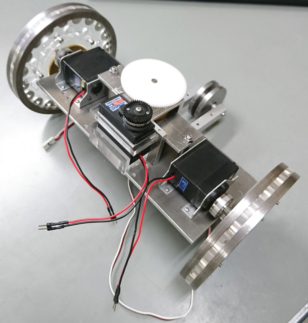
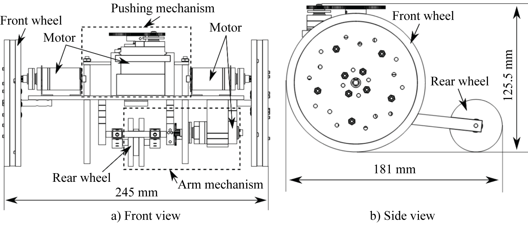
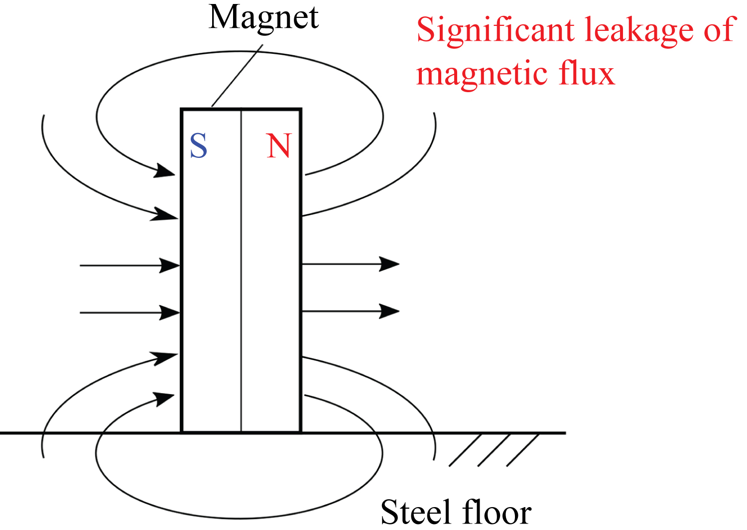
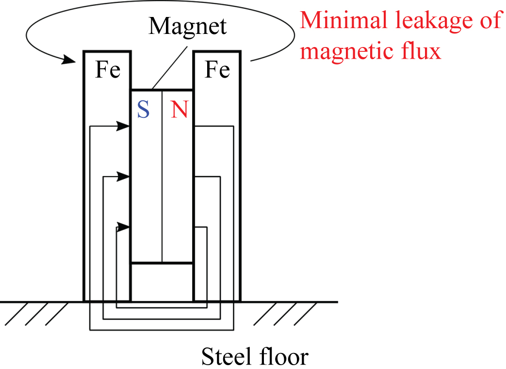
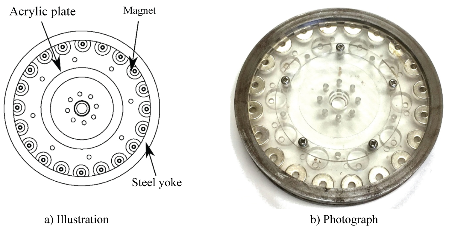

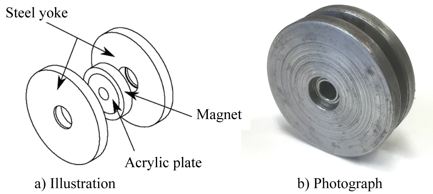
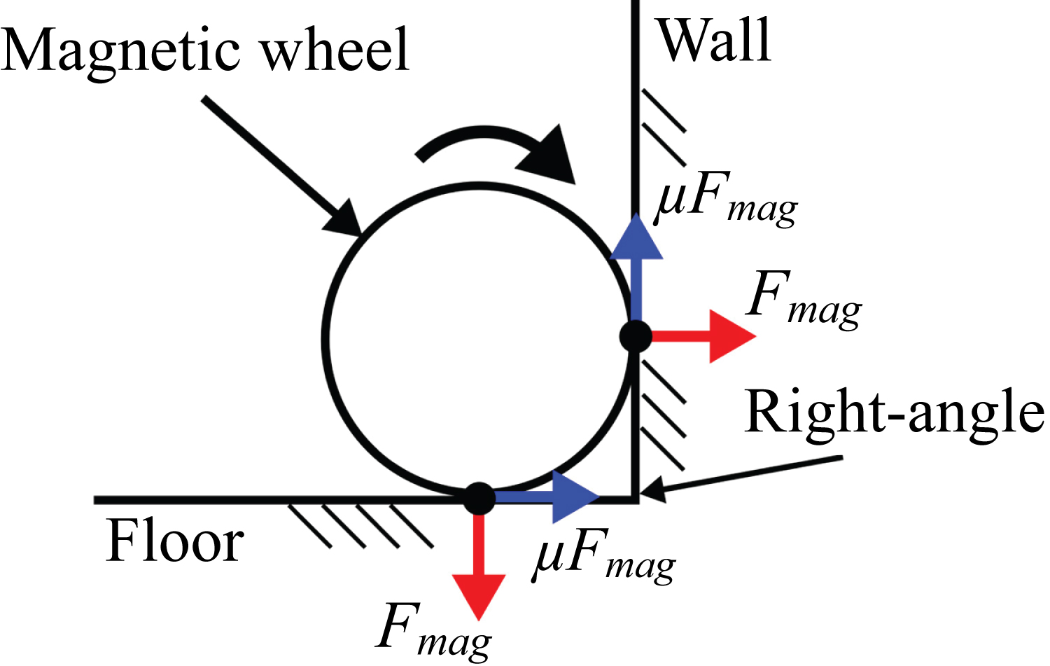
Figure 8: Dynamic model of a magnetic...
Dynamic model of a magnetic wheel adhering to two surfaces at a right-angled juncture.
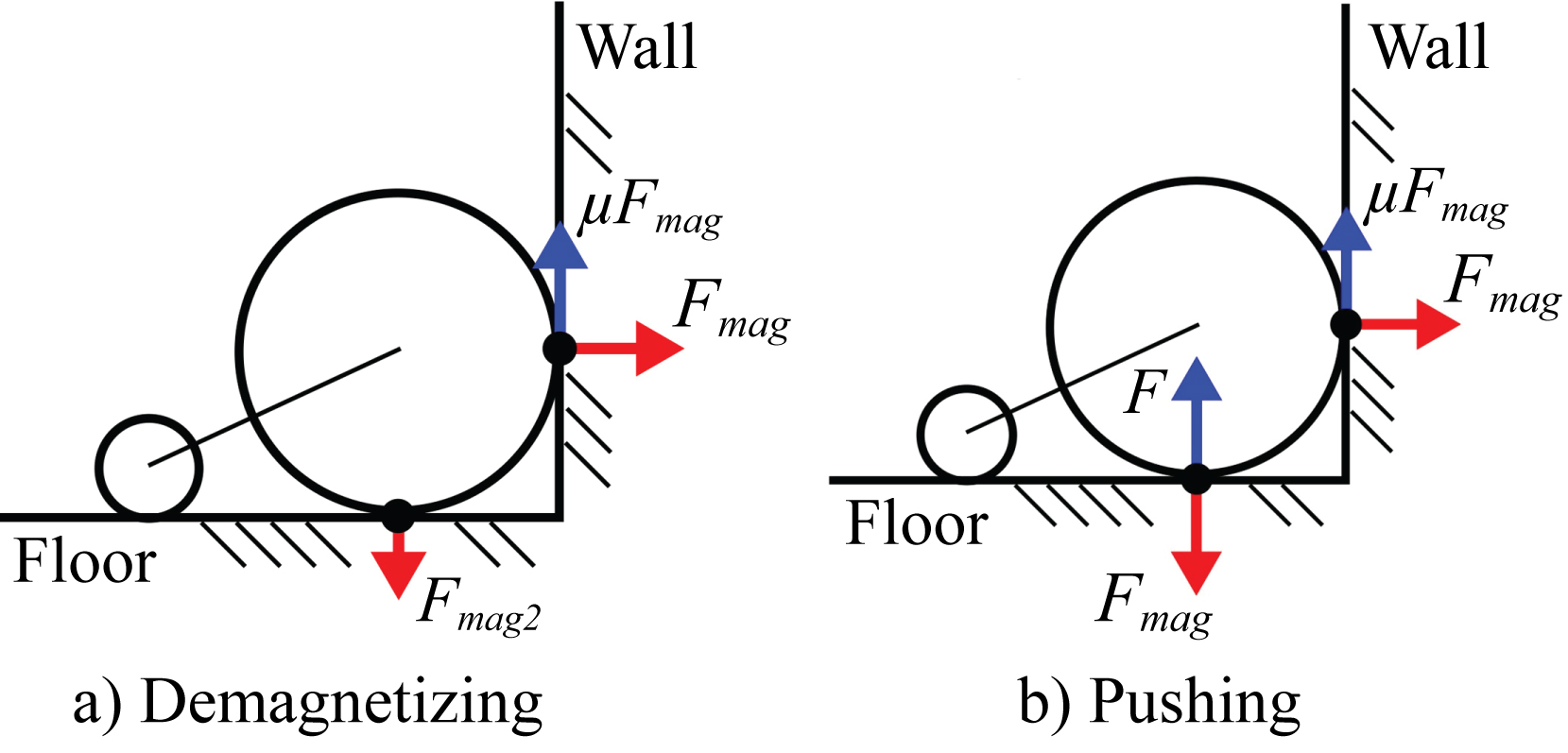
Figure 9: Methods of peeling the...
Methods of peeling the magnetic wheels away from one surface at a right-angled juncture.
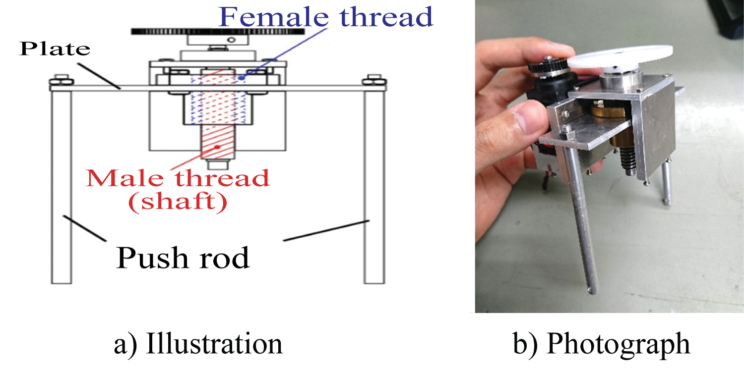

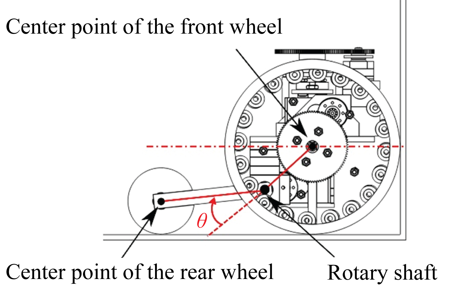
Figure 12: Relationship between the...
Relationship between the wheels and the arm mechanism (θ = -22.5°).

Tables
Table 1: Specifications of the magnetic-wheeled robot.
Table 2: Result of experiments to measure the carrying capacity of the robot.
Table 3: Result of experiments of traveling on the paths that included a right-angled juncture.
References
- (2009) The maintenance of national road network in Japan. Japanese Ministry of Land, Infrastructure and Transport Road Bureau.
- T Yamaguchi (2010) Life cycle management of bridge structures. Symposium on Evaluation and Diagnosis 9: 6-9.
- (2014) Bridge periodical inspection procedure. Japanese Ministry of Land, Infrastructure and Transport.
- W Shen, J Gu, Y Shen (2006) Permanent magnetic system design for the wall-climbing robot. Applied Bionics and Biomechanics 3: 151-159.
- HM La, TH Dinh, NH Pham, QP Ha, AQ Pham (2016) Automated robotic monitoring and inspection of steel structures and bridges. Robotica 1-21.
- M Wakayama (2016) Inspection by "Bridge Dragon", the Bridge Inspection Robt System. Journal of the Robotics Society of Japan 34: 575-576.
- H Leon-Rodriguez, S Hussain, T Sattar (2012) A compact wall-climbing and surface adaptation robot for non-destructive testing. 12th International Conference on Control, Automation and Systems, 404-409.
- M Tavakoli, C Viegas, L Marques, JN Pires, ATD Almeida (2013) OmniClimbers: Omni-directional magnetic wheeled climbing robots for inspection of ferromagnetic structures. Robotics and Autonomous Systems 61: 997-1007.
- ST Nguye, HM La (2018) Design and development of a flexible steel surface climbing inspection robot.
- Y Takada, K Kirimoto, T Tajiri, T Kawai (2013) Development of a bridge inspection robot working in three-dimensional environment (Evaluation of driving performance of a moving mechanism with permanent magnets). Transactions of the Japan Society of Mechanical Engineers C 79: 3135-3146.
- Y Takada, S Ito, N Imajo (2017) Development of a bridge inspection robot capable of traveling on splicing parts. Inventions 2: 22.
- Engineering toolbox, Permeability.
Author Details
Yodai Matsumura1, Takehiro Shiba2, Satoshi Ito1, Yuya Kawase1 and Yogo Takada1*
1Department of Mechanical and Physical Engineering, Osaka City University, Japan
2Industrial Measurement Co., Ltd, Japan
Corresponding author
Yogo Takada, Department of Mechanical and Physical Engineering, Osaka City University, 3-3-138 Sugimoto, Sumiyoshi-ku, Osaka-shi, Osaka, 558-8585, Japan.
Accepted: September 18, 2018 | Published Online: September 20, 2018
Citation: Matsumura Y, Shiba T, Ito S, Kawase Y, Takada Y (2018) Development of Magnetic Bridge Inspection Robot Aimed at Carrying Heavy Loads. Int J Robot Eng 3:010.
Copyright: © 2018 Matsumura Y, et al. This is an open-access article distributed under the terms of the Creative Commons Attribution License, which permits unrestricted use, distribution, and reproduction in any medium, provided the original author and source are credited.
Abstract
This paper presents a bridge inspection robot capable of traveling on inner right-angled paths. Locomotion of the newly developed robot is achieved via two motor-driven wheels that are composed of steel yokes, acrylic plates, and neodymium magnets. When the wheel contacts a steel plate, it forms a magnetic circuit and generates a strong force. Owing to this force, the robot can move with heavy objects attached. However, when the wheels strongly adsorb on two surfaces at right-angled junctures, the robot becomes unable to move. To peel the wheels away from one surface, a mechanism is needed to eliminate the strong magnetic force. To achieve this, the robot has been equipped with a pushing mechanism that allows for travel on any inner right-angled path. In this study, the performance of the robot was tested on a steel box that imitated a box girder. The robot was able to carry heavy objects, and it also showed an ability to travel along paths that included a right-angled juncture by utilizing the pushing mechanism.
Keywords
Mobile robot, Bridge inspection, Magnetic robot, Pushing mechanism, Two-wheel drive robot
Introduction
In recent years, infrastructure, such as bridges and tunnels, has been aging in Japan. Most of these structures were built during periods of economic growth, but more than 50 years have passed, which is equivalent to the useful lifespan of most bridges [1]. Therefore, it is necessary to take measures against the aging of these structures [2]. As one of those measures, periodic inspections have been conducted to find and repair minor damage early [3]. However, this is a costly and time-consuming process that also carries the risk of workers falling from high places. Therefore, inspections using robots, which lower costs and improve safety, have been attracting attention.
Various robots have been developed to inspect steel bridges [4-9]. Most of these robots can carry out these inspections while loaded with heavy objects such as cameras and other inspection equipment since they can absorb to bridges via a strong magnetic force. However, they can examine only a small portion of the desired inspection area, such as flat sections or deck sections.
We have designed and built various magnetic robots that can inspect a variety of areas [10,11]. These robots can travel on complex three-dimensional paths because they are equipped with magnetic, rimless wheels. The special-shaped wheel generates a sufficiently large frictional force between itself and the wall surface when it rotates. As a result, robots such as BIREM-III have exhibited high performance on paths that include inner right-angled junctures, which imitate the three-dimensional environment of bridges.
However, since these robots have poor loading capability, inspection equipment such as cameras and sensors that they can be equipped with is limited.
Therefore, in this study, we aimed to develop a magnetic bridge inspection robot capable of carrying heavy payloads. We confirmed that the robot was able to travel on paths similar to those found on a bridge, including those with right-angled junctures.
Materials
Figure 1 shows the photograph of the robot we designed, Figure 2 shows its structure, and Table 1 shows its specifications. The robot has four main components: Two front magnetic wheels, a rear magnetic wheel, a pushing mechanism for peeling the front wheels away from a steel surface at a right-angled juncture, and an arm mechanism supporting the rear wheel.
Front magnetic wheel
A magnetic bridge inspection robot needs to travel on inspection paths with sensors to find cracks or corrosion points. Therefore, its wheels should be capable of generating a strong adherence force.
The adherence force generated by a magnet increases as the number of lines of magnetic force passing through the attracting surface increases. When a magnet contacts a steel plate, most of the magnetic flux passes through the air, and only a portion of it passes through the plate (Figure 3). This indicates that the magnetic flux leakage is large. To generate a strong attractive force, it is necessary to reduce this leakage.
One of the methods for reducing this leakage is to sandwich both the left and right sides of the magnet between steel yokes. This causes more lines of magnetic flux to pass through a steel plate (Figure 4) because the permeability of steel is higher than that of air [12]. Therefore, the amount of leakage flux decreases, and the magnet generates a strong attractive force.
The front magnetic wheel is composed of twenty permanent magnets, a pair of steel yokes, and an acrylic plate (Figure 5). The magnets are ring-shaped neodymium magnets with an outer diameter of 12 mm, an inner diameter of 3 mm, and a thickness of 5 mm. The steel yoke is a ring made of SS400 with an outer diameter of 118 mm, an inner diameter of 104 mm, and a thickness of 5 mm. The acrylic plate is used to arrange the magnets only at the outer peripheral part, which makes its adherence force stronger while maintaining its weight.
To measure the adherence force of the magnetic wheel, an experiment was conducted. Figure 6 shows the experimental equipment. It is composed of a pre-painted steel plate (thickness 2 mm), a digital force gauge FGP-50 (Nidec-Shimpo Corporation, Kyoto), and a magnetic wheel (Figure 6a). The measurements were carried out in the following procedure. Firstly, the magnetic wheel was placed in the inner region of the masking tape of the steel plate placed on the floor (Figure 6b). Secondly, the string attached to the wheel was pulled vertically upward with a force gauge and the wheel was peeled off from the steel plate. Then, the peak value of the force gauge was recorded. The experiment was conducted ten times. Then, the value obtained by subtracting the wheel weight from the average value was used as the adherence force. As a result, this wheel exhibited a magnetic adherence force of 173.5 N with a mass of only 0.391 kg.
Rear magnetic wheel
The rear magnetic wheel is composed of a permanent magnet, a pair of steel yokes, and an acrylic plate (Figure 7). The magnet is a ring-shaped neodymium magnet with an outer diameter of 25 mm, an inner diameter of 19 mm, and a thickness of 5 mm. The yoke is a ring made of SS400 with an outer diameter of 45 mm and a thickness of 5 mm. The acrylic plate fixes the position of the magnet. The magnetic force of the rear wheel was measured by the same experiment as the front wheel. The mass of the rear wheel is 0.140 kg, and its adherence power is 61.1 N.
Pushing mechanism
A bridge inspection robot needs to be able to run through complicated inspection paths that can include right-angled junctures. However, wheel-type robots cannot travel on such paths using only their own driving force because their wheels strongly adhere to two surfaces at right-angled junctures. Figure 8 shows forces acting on the wheel at a right-angled juncture. To peel the wheels away from one wall to allow the robot to move to another wall, their magnetic force, Fmag needs to at least satisfy the following equation:
However, since the friction coefficient, µ, is less than 1, the robot is unable to travel on such paths by itself.
There are two ways to allow wheel-type robots to move along paths that include an inner right-angled juncture. One method is to weaken the magnetic force at the right-angled juncture (Figure 9a). This has the disadvantage of making the structure of the magnetic wheel more complicated. Additionally, it is difficult to weaken only the adherence force with the intended surface. Another method is to push away from the wall surface to peel the wheels away from it (Figure 9b). In this method, the robot pushes away from the wall surface using a pushing mechanism, making the reaction force greater than the attraction force. This offers the advantage of a simpler mechanism compared to the first method. In this study, therefore, we equipped the robot with a pushing mechanism.
The pushing mechanism is composed of a trapezoidal screw, a pair of pushing rods, a motor, and a reduction mechanism (Figure 10). First, the rotational motion of the motor is transmitted to the female screw via the reduction mechanism. Second, the push rods contact the wall surface and hinder the rotational movement of the female screw. As a result, the entire female screw moves rectilinearly, and the rods push away from the wall surface strongly. The mechanism mounted on the robot can push outwards with a maximum force of 490 N.
Arm mechanism to rotate rear wheel support
The arm mechanism to rotate the rear wheel support is composed of a servo motor, a rotary shaft, a reduction mechanism, and a pair of arms supporting the rear wheel (Figure 11). This arm mechanism enables us to change the distance between the front and rear wheels by rotating the arm supporting the rear wheel. The reduction mechanism has a ratio of 4. The range of the arm angle, θ is ± 22.5°. When the angle θ is -22.5°, the chassis is horizontal to the surface with which the front wheels are in contact (Figure 12).
Methodology
Electronics circuits to control the robot
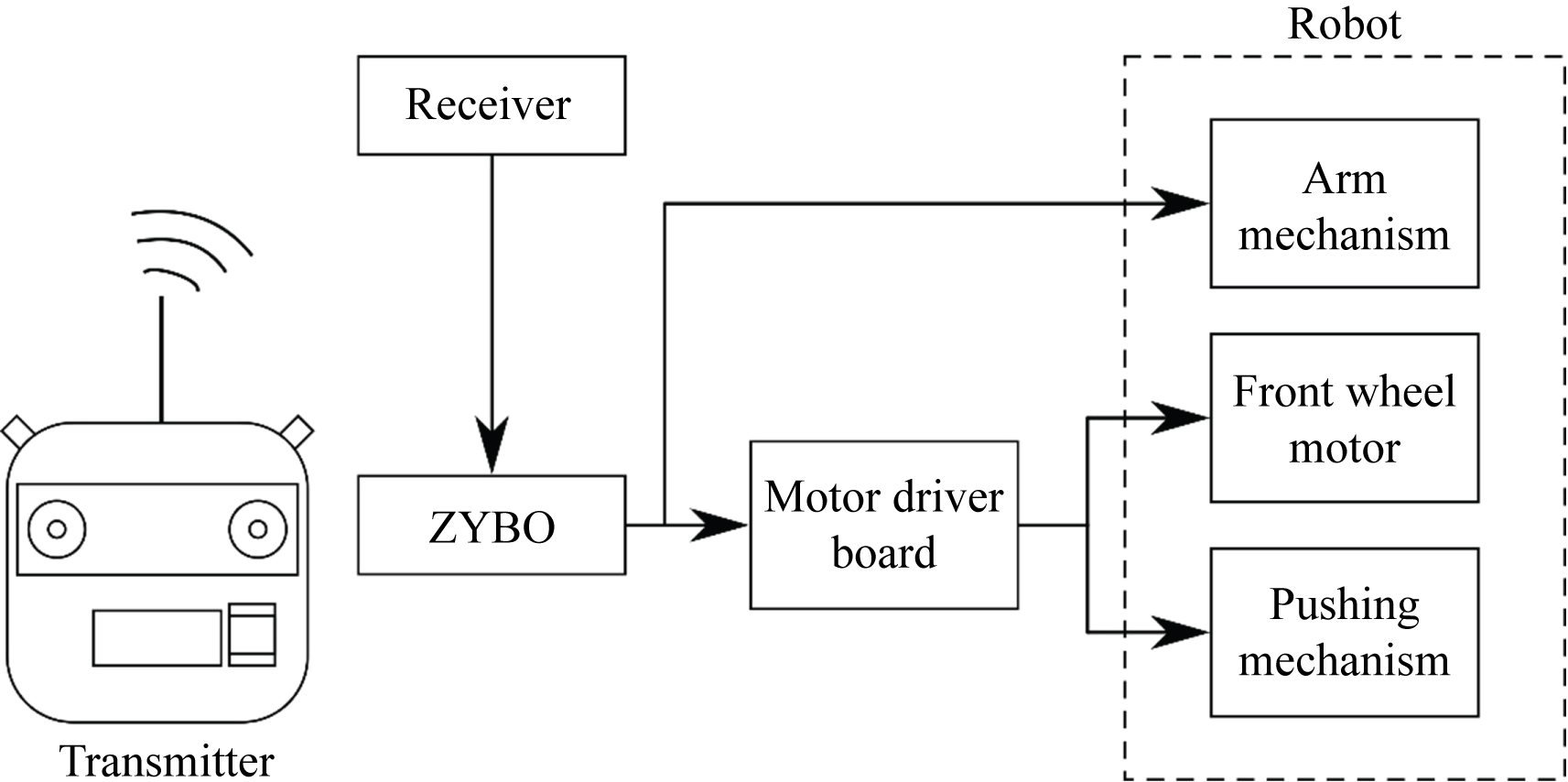
A control system is mounted outside of the robot. The system is composed of a ZYBO (Digilent, Pullman, Washington, United States), a motor driver board for driving the front wheels, a regulator board, a paired transmitter and receiver (Futaba, Chiba, Japan), and a stabilized DC power supply (Matsusada Precision, Shiga, Japan). The stabilized DC power supply and the regulator board supply power to the motor driver board and the receiver. The transmitter's signal is received at the receiver, and the ZYBO processes it and sends signals to the motor driver board. According to the signals, the motor driver board drives the front wheels and activates the pushing mechanism. In addition, the ZYBO activates the arm mechanism according to the signal from the receiver. This system enables remote control of the robot via the transmitter (Figure 13).
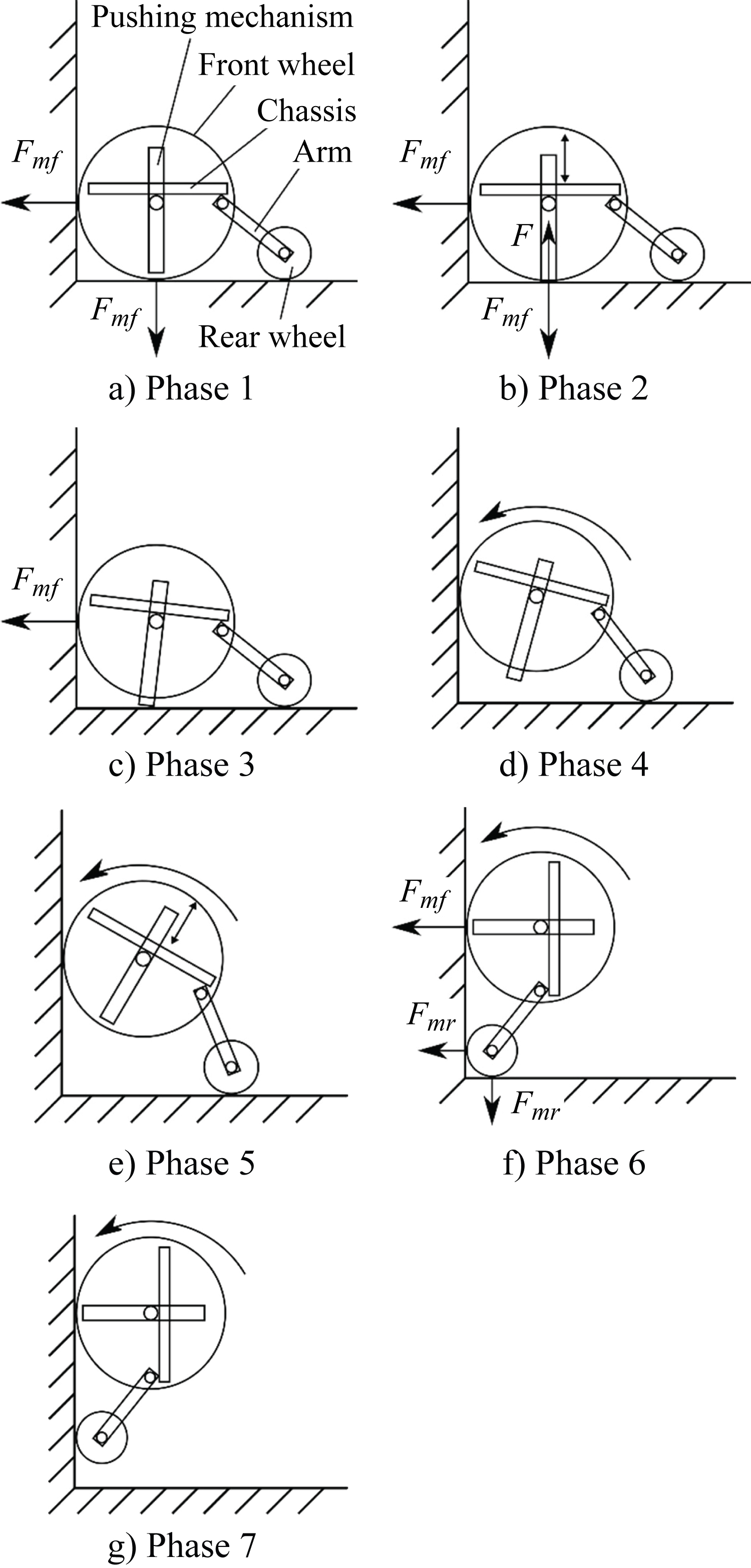
Transition method at right-angled juncture
At an inner right-angled juncture, the robot runs through the following process. First, the robot is advanced toward the right-angled juncture until both front wheels contact the next wall (Figure 14a). Then, the front wheels are peeled away from the first wall using the pushing mechanism (Figure 14b, Figure 14c and Figure 14d). Third, the pushing rods are returned to their initial position to prevent contact with either wall (Figure 14e). Fourth, the robot is advanced forward again. Then, the rear wheel adheres to both of the walls (Figure 14f). However, the rear wheel is smoothly peeled away from the first side since its magnetic force is weak. Finally, the robot can change walls (Figure 14g).
Discussion
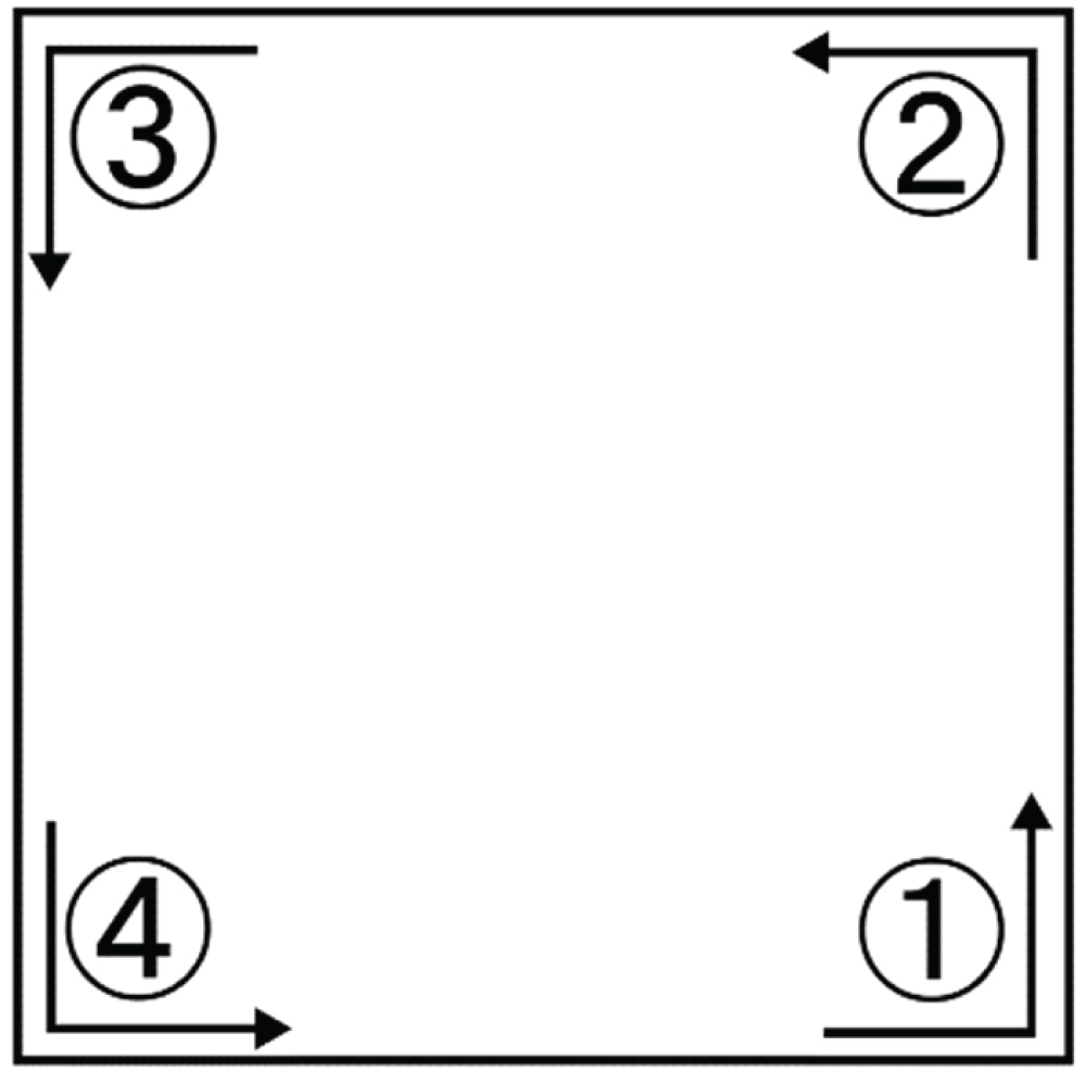
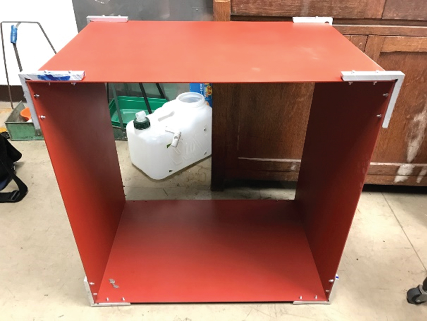
To assess the performance of the robot, two types of experiments were conducted. In the first experiment, the weight the robot could carry was measured. In the other experiment, the ability of the robot to travel inner right-angled junctures such as in paths 1 through 4 was confirmed (Figure 15). Both experiments were conducted on a small steel box within a laboratory environment. The box was composed of four steel plates with a length of 600 mm, a width of 400 mm, and a thickness is 2.3 mm (Figure 16).
Experiments to measure carrying capacity
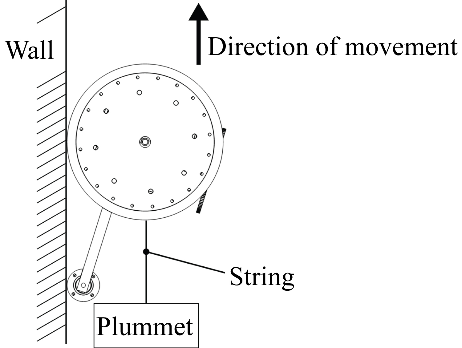
In this experiment, the weight that the robot could carry was measured. First, the robot was placed on the steel wall. Next, the plummet was attached to the robot. Then, the stabilized power supply was turned on, and the robot began to move (Figure 17). During this experiment, the power supply voltage was 7.4 V. To compare climbing ability under different conditions, the locomotive speed of the robot was measured.
In this experiment, it became clear that the robot was able to carry 2 kg. Table 2 shows the climbing speed of the robot under different conditions. As the mass of the plummet increased, the climbing speed decreased. However, the robot ran at sufficient speed even with a plummet of 2.010 kg attached.
Experiments of traveling on a path that included a right-angled juncture
In this experiment, the locomotive performance on a path that included a right-angled juncture was confirmed. First, the robot was placed at the start of a path. Next, the robot was advanced along the path toward a right-angled juncture. At that point, the pushing mechanism was operated to peel away the front wheels from the first surface. Then, the robot was advanced farther. Finally, the rear wheel was pulled away from the first surface, and the robot continued along the path. In this experiment, an experimenter maneuvered the robot while viewing it. In addition, the robot was tested without a weight attached. The experiment was conducted ten times for each path. Then, the percentage of travel without incident, such as falling from the surface of the wall, was calculated.
Table 3 shows the results of this experiment, which indicated two things. First, it was confirmed that the robot was able to cancel the strong adherence between the front wheels and the wall surface by using the pushing mechanism. Second, as Table 3 indicates, the robot was able to travel with a high success rate on all of the paths. However, the robot fell one time from the surface of the wall on path 3.
There are two mechanisms that the robot fails on path 3: Slipping down and rotation (Figure 18).Firstly, the robot slips down and falls if the friction force acting between the front wheels and the wall surface is insufficient (Figure 18a). However, the front wheels have produced sufficient frictional force in the experiments to measure carrying capacity. Therefore, we have concluded that the slipping down is not the cause why the robot has failed traveling on path 3.
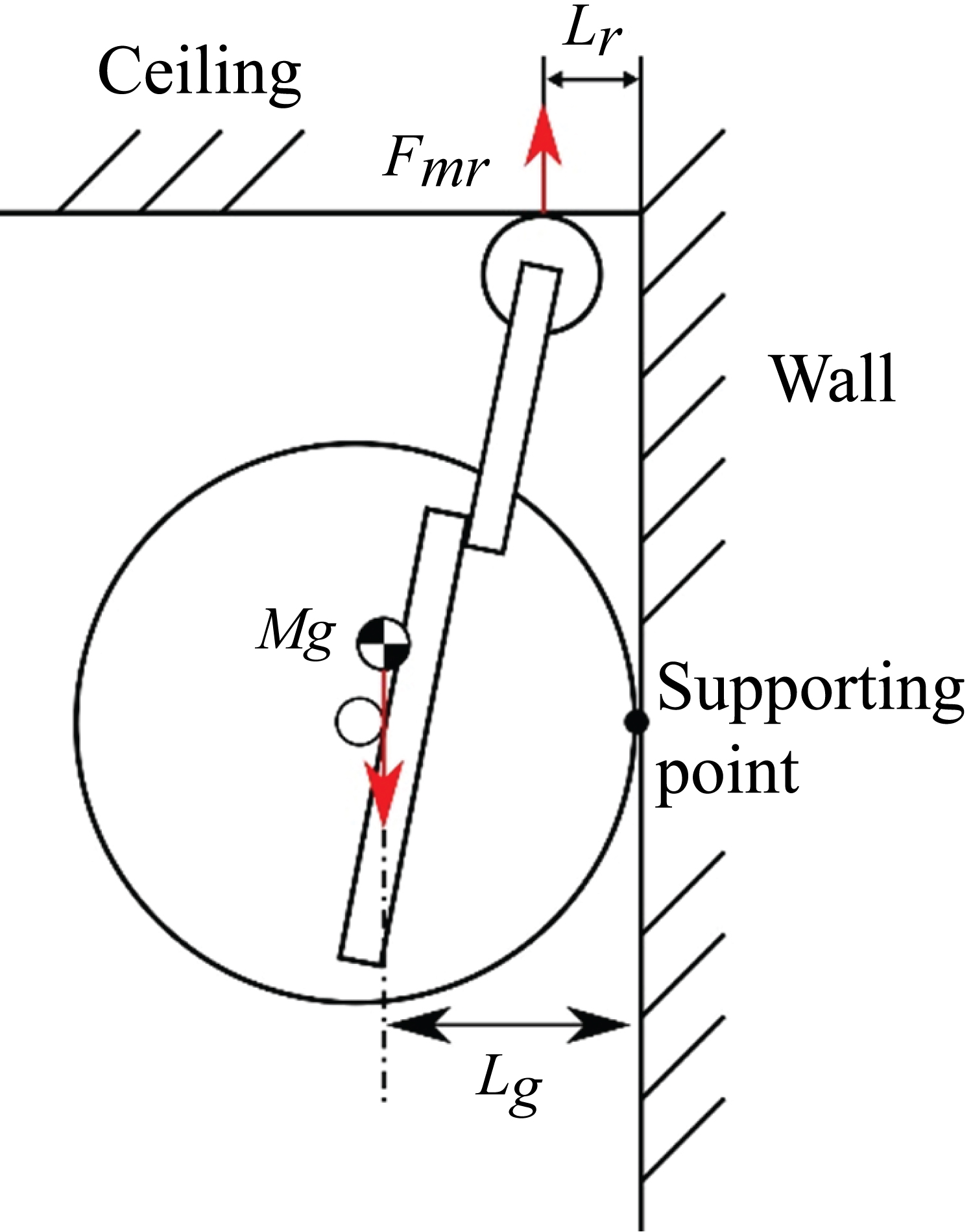
Secondly, the robot rotates around the contact point between the front wheels and the wall surface as the rotation center if the magnetic force of the rear wheel is insufficient (Figure 18b). Figure 19 shows the dynamic model of the robot traveling on path 3. In Figure 19, Fmr is the magnetic force of the rear wheel, M is the total mass of the robot, g is the gravitational acceleration, Lr is the distance between the wall surface and the contact point of the rear wheel, and Lg is the distance between the wall surface and the center of gravity of the robot. If the attraction force of the rear wheel is insufficient, the entire robot rotates around the contact point of the front wheels and the rear wheel disengages from the ceiling surface. And, the robot needs to satisfy equation (2) to prevent this type of rotation. According to equation (2), this rotation occurs regardless of the frictional force acting between the front wheels and the wall surface. In addition, the rear wheel does not adhere well to the ceiling surface when a roll angle occurs. Then, the magnetic force of the rear wheel sharply decreases, and the equation (2) comes not to hold. Therefore, we have concluded that the lack of the rear wheel is the cause why the robot has failed traveling on path 3.
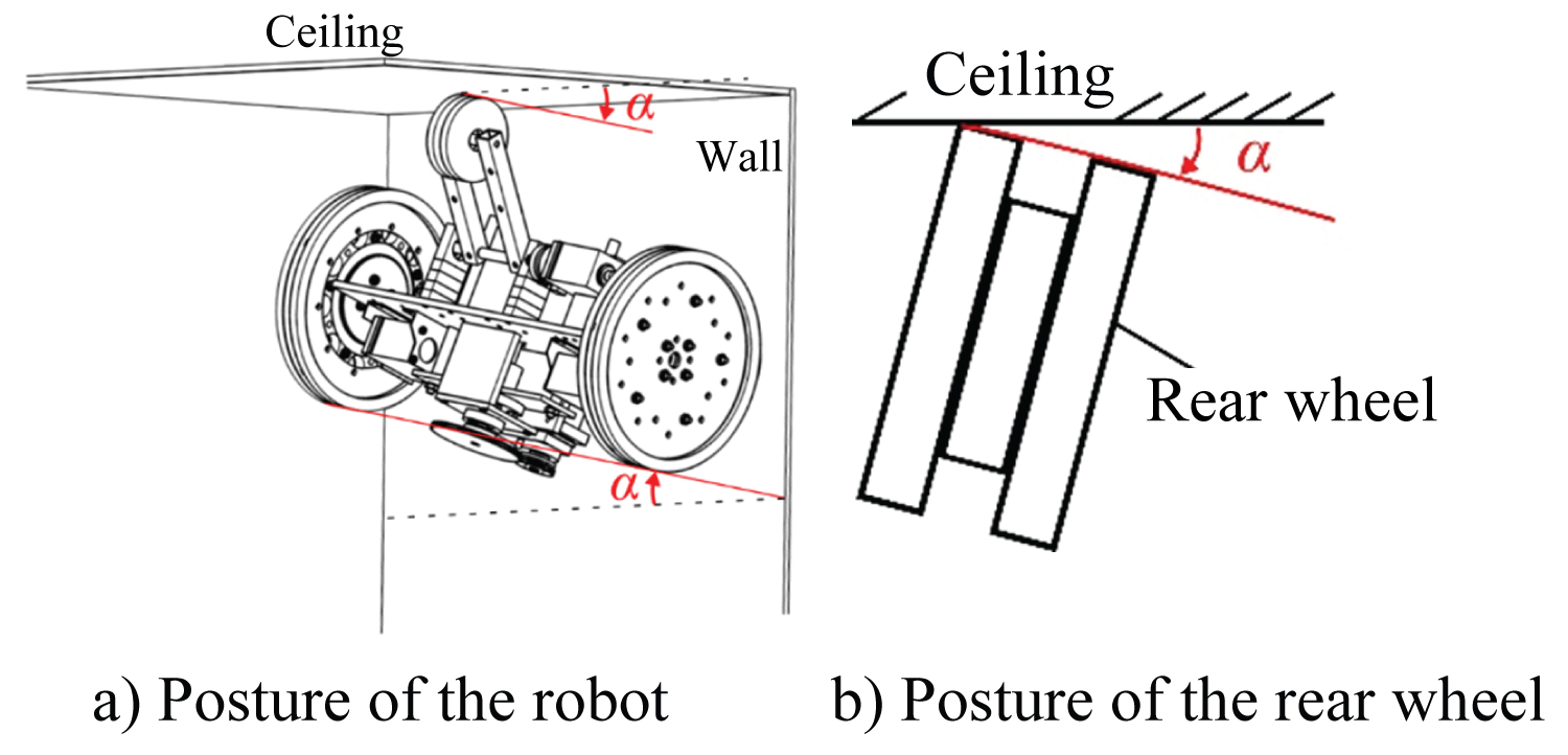
The lack of magnetic force in the rear wheel was caused by the following process. First, the front wheels were peeled away from the ceiling surface by the pushing mechanism. At this time, a roll angle α was caused by the asymmetry of the strength of the attraction force of both wheels or the asymmetry of the pushing mechanism (Figure 20a). Then, due to the roll angle α, the contact angle of the rear wheel changed, and one side of its yoke dropped from the ceiling surface (Figure 20b). As a result, the magnetic force of the rear wheel decreased markedly.
To prevent this rotation from occurring, we propose the following two adjustments. The first is to increase the degree of freedom of the arm mechanism. Therefore, even when a roll angle α occurs, the rear wheel can maintain proper contact with the wall surface. However, this method has the disadvantage of making the arm mechanism more complicated, larger, and heavier. Another method is to maintain the roll angle α at zero. Although the robot needs to be equipped with a posture detection sensor, it is unnecessary to otherwise significantly change its structure. Thus, this method has the advantage of effectively maintaining the weight of the robot. By adopting the latter of these methods, the locomotive performance on path 3 improves.
Conclusion
In this study, we aimed to develop a magnetic bridge inspection robot that is able to carry heavy loads.
First, we designed a magnet wheel that combined neodymium magnets and steel yokes. The wheel forms a magnetic circuit when it contacts a steel plate and produces a strong magnetic force that allows the robot to carry heavy loads. It was confirmed that the robot was able to travel vertically upward on a steel plate even when carrying a 2-kg load.
Second, a pushing mechanism was mounted on the robot. With the mechanism, the robot was able to peel away the front wheels when they were strongly adhering. As a result, the robot was able to travel along paths that included inner right-angled junctures.
Third, the robot fell one time while traveling on the path moving from the ceiling to the wall. The cause of the fall was that the attraction force of the rear wheels decreased at the right-angled juncture. To prevent this from occurring, it is necessary to maneuver the robot carefully so as not to generate roll angle α. Therefore, maneuvering the robot is more difficult when traveling on path 3 than when traveling on other paths.
In the future, we hope to improve the robot so that it is capable of traveling on paths that include inner right-angled junctures more successfully and more easily. For that purpose, a further study of controlling either the robot's posture or the arm mechanism should be conducted.