
International Journal of Magnetics and Electromagnetism
(ISSN: 2631-5068)
Volume 5, Issue 2
Research Article
DOI: 10.35840/2631-5068/6522

Article Formats
On the Magnetic Designing of Compact Alpha-Magnets
Table of Content
Figures
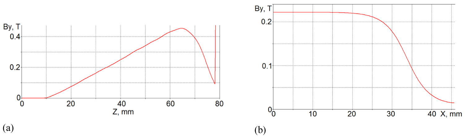
Figure 1: Vertical field [T] in the permanent....
Vertical field [T] in the permanent alpha-magnet along the big a) and small (at 27 mm distance) axes b) of the "α-leaf" trajectory.
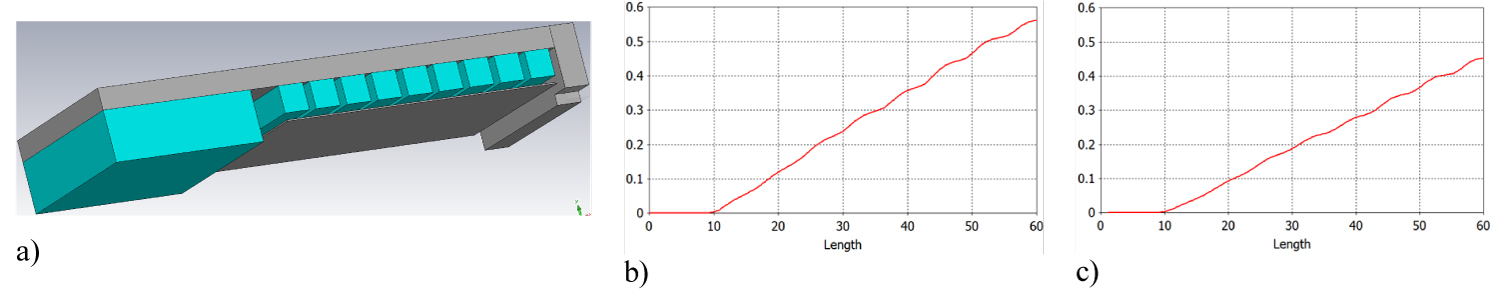
Figure 2: a) PM α-magnet design with 0.25 mm thick...
a) PM α-magnet design with 0.25 mm thick mild steel insert, magnetic gap 6 mm, 9 mm minimum distance between the 9 + 9 PM NdFeB N52 grade blocks having 1.46 T magnetization and 6.4 mm period; b) Vertical magnetic field by simulated along the axis of symmetry with the insert (6 mm magnetic gap); c) The same without the insert (i.e. 9 mm magnetic gap).
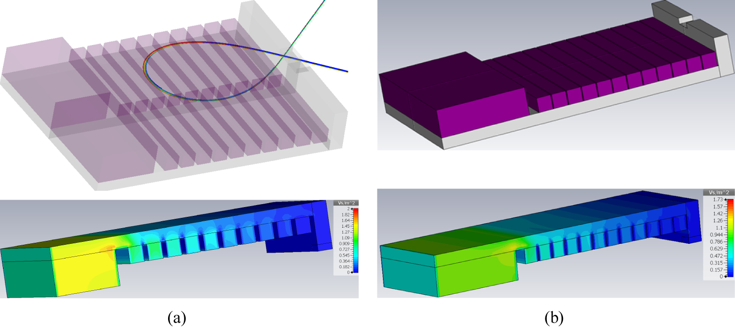
Figure 3: Magnetic design of two permanent alpha-magnets...
Magnetic design of two permanent alpha-magnets with tapered magnetization between the PM blocks, steel yoke of 67 mm width. TOP: Lower half of the α-magnet with 1.8 MeV beam trajectory simulated in the design a) Having 10 + 10, 5 × 5 mm2 PM blocks, 12 mm magnetic gap, 6.4 mm period, and three N52 grade blocks (1.46 T maximum magnetization, one half view) and α-magnet; b) With 12 + 12, 5 × 5 mm PM blocks, 9.5 mm magnetic gap, 5.375 mm period, and three low grade 28UH magnets (1.04 T maximum magnetization). BOTTOM: One-quarter view of absolute magnetic field induction.
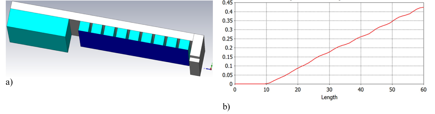
Figure 4: PM α-magnet design similar to that of....
PM α-magnet design similar to that of Figure 2a but with 150 microns μ-metal sheet covering the poles (a) and vertical magnetic field by simulated along the axis of symmetry (b).
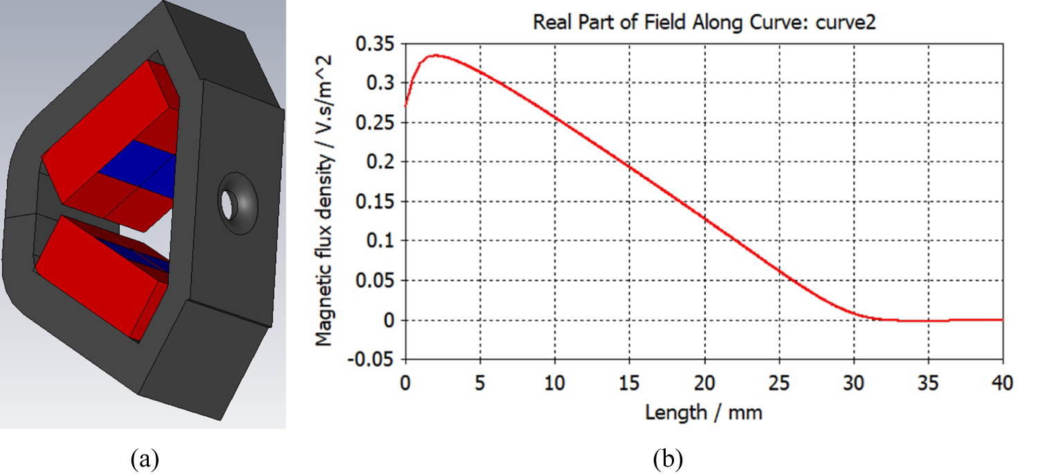
Figure 5: Permanent alpha-magnet concept with...
Permanent alpha-magnet concept with a high gradient provided by yoke and tilted block a) Beam aperture is 6 mm. Magnetic field by [T] plotted along the axis of symmetry; b) Field accuracy is better than 1% in the good filed region inside the magnet is achieved with using μ-metal pad placed in the middle of the magnet. PM block magnetization is 1.25 T.
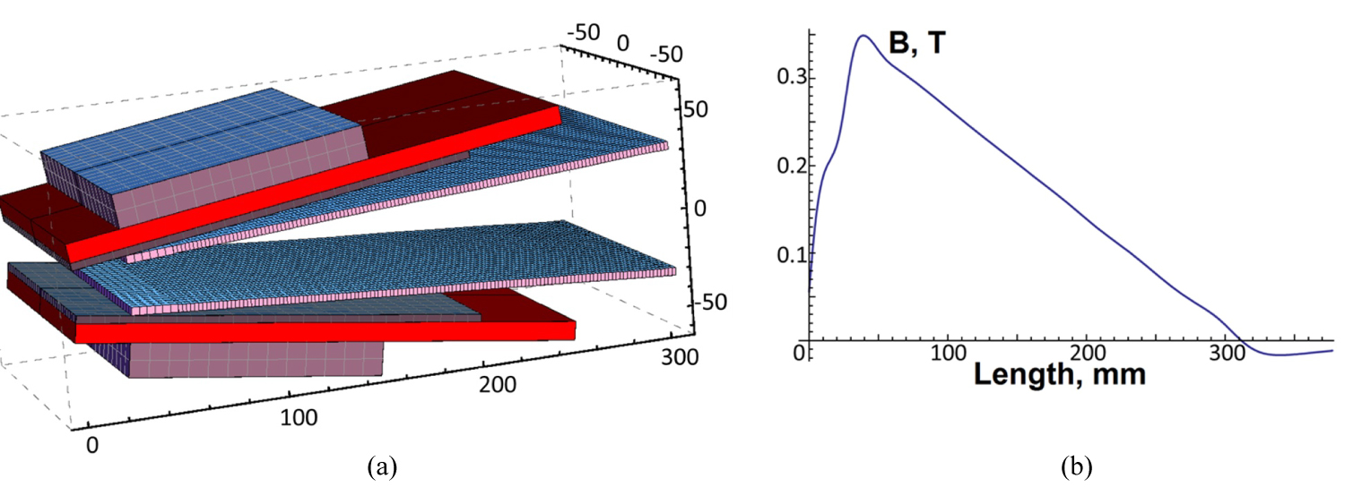
Figure 6: A conceptual design of PM-alpha magnet...
A conceptual design of PM-alpha magnet with 28 cm depth and 2.5 T/m field gradient a) and magnetic field plot along the axis of symmetry; b) Minimum magnetic gap 22 mm. Permanent magnet magnetization. 1.25 T. Internal thin plates are made from Permendur. External thick blocks as well as the plate between the permanent magnet and the Permendur plate are made from soft steel. Simulated with the Radia code.
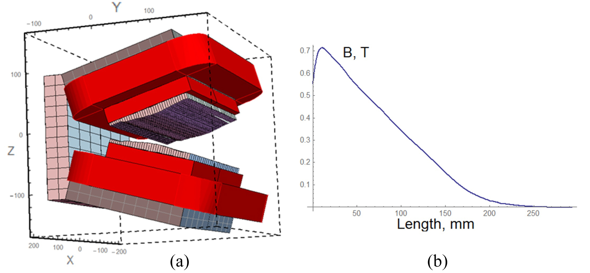
Figure 7: "Open mouth" design of PM-dominated α-magnet...
"Open mouth" design of PM-dominated α-magnet (a) with trimming coil and specially profiled pole to lineraize goot field region. Vertical component of magnetic field plotted along the axis of symmetry (b).
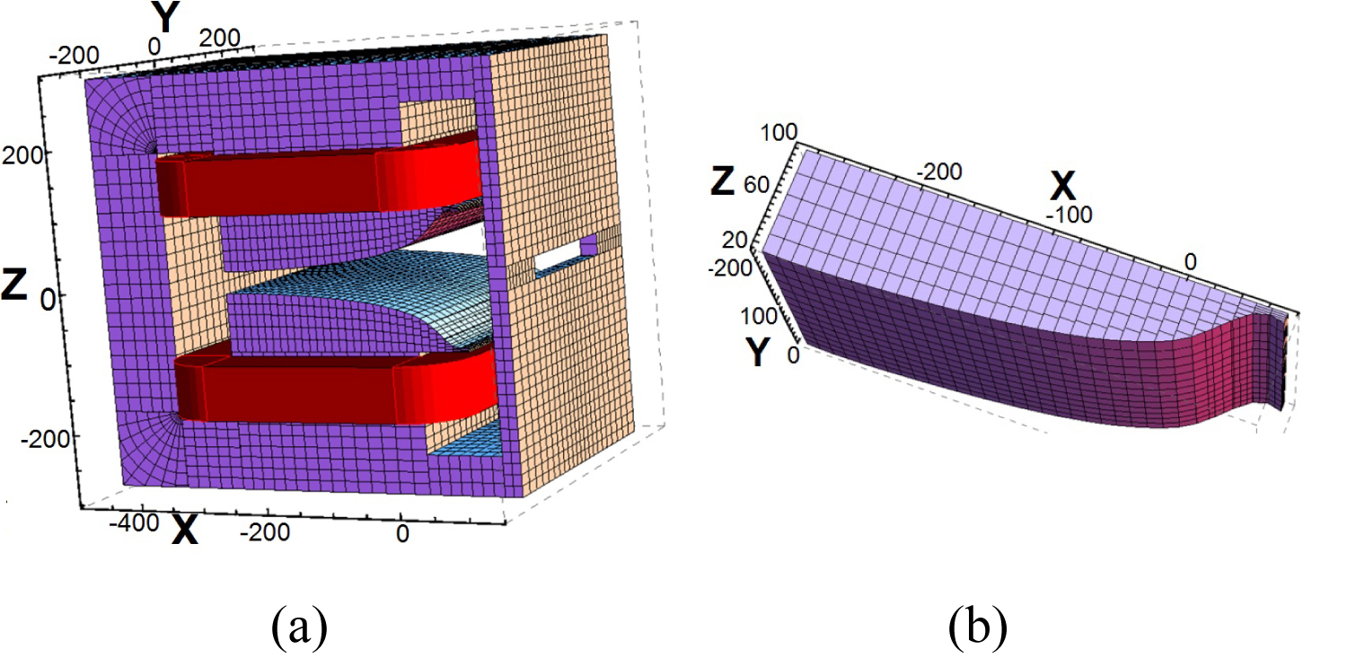
Figure 8: Radia model of alpha-magnet with 34 cm depth...
Radia model of alpha-magnet with 34 cm depth and 31.8 mm minimal gap (a) and its pole (b).
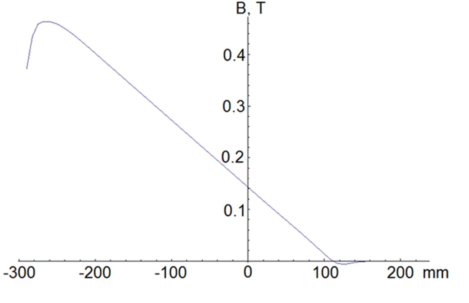
Figure 9: Magnetic field plot along the axis of...
Magnetic field plot along the axis of symmetry for the design of Figure 7.
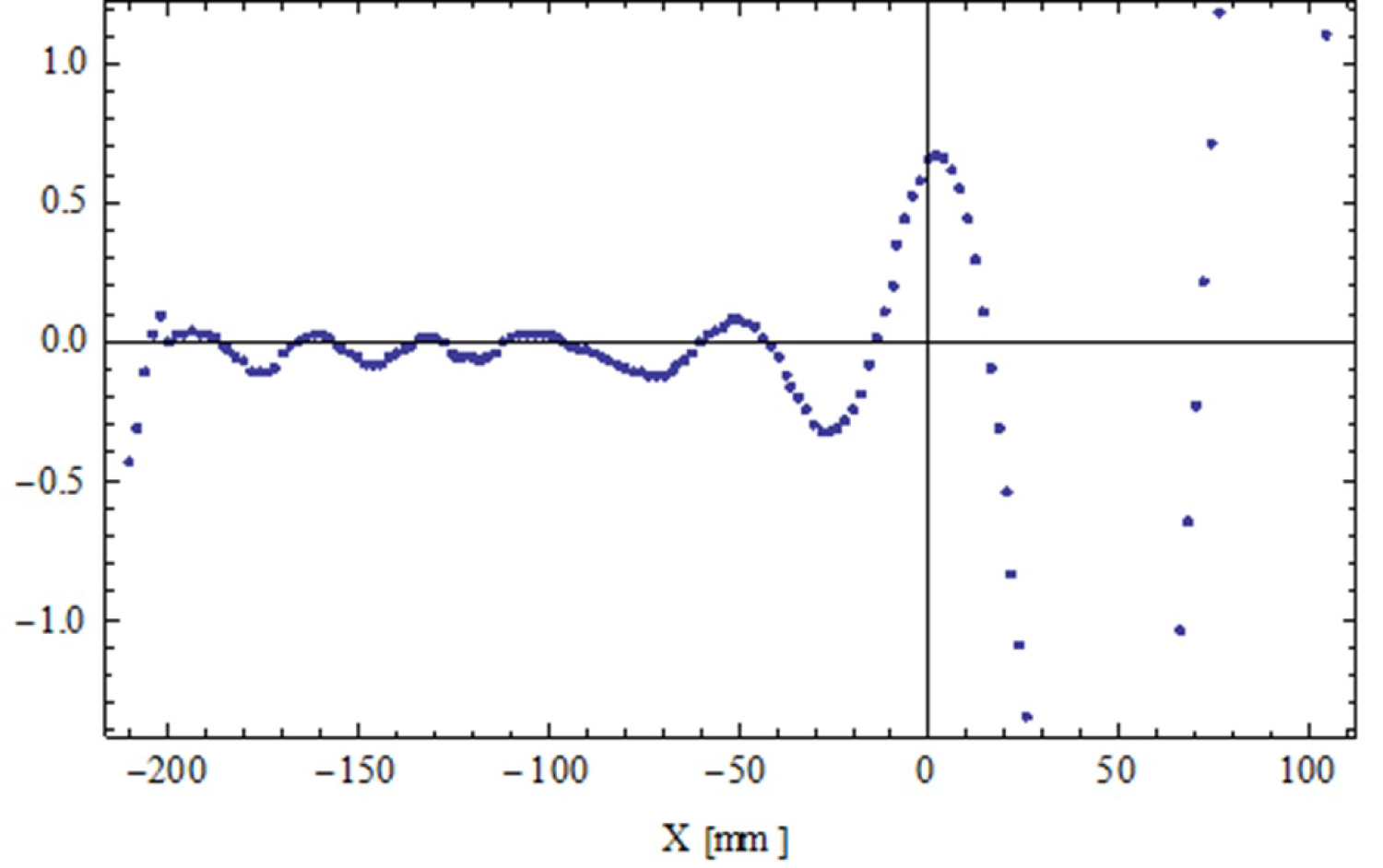
Figure 10: Field gradient relative deviation [%] from...
Field gradient relative deviation [%] from ideal magnet with respect to the maximum field along the axis of symmetry for the design of Figure 7.
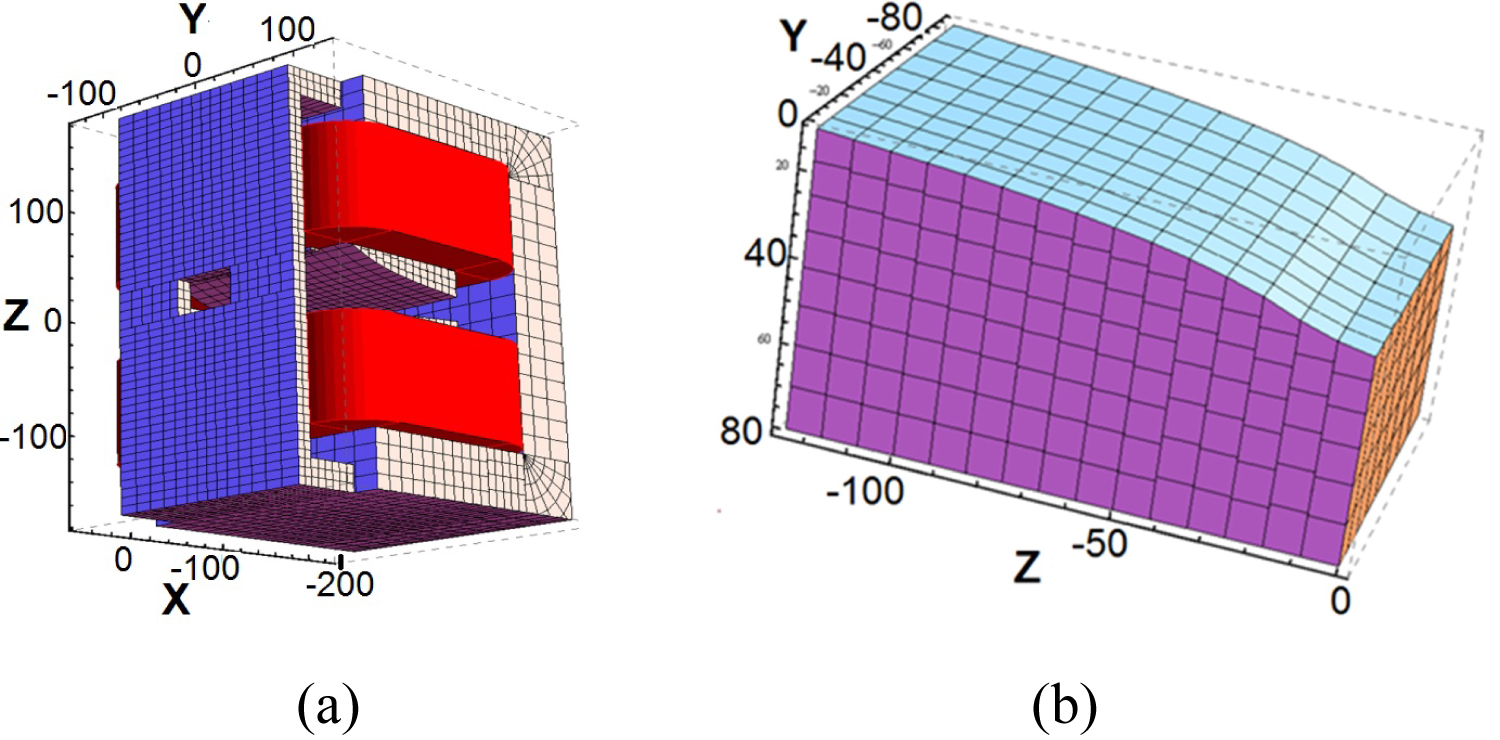
Figure 11: Radia model of a 15 cm depth, 35 cm height...
Radia model of a 15 cm depth, 35 cm height, and 21.6 mm minimal gap alpha-magnet (a) and its pole shape (a).
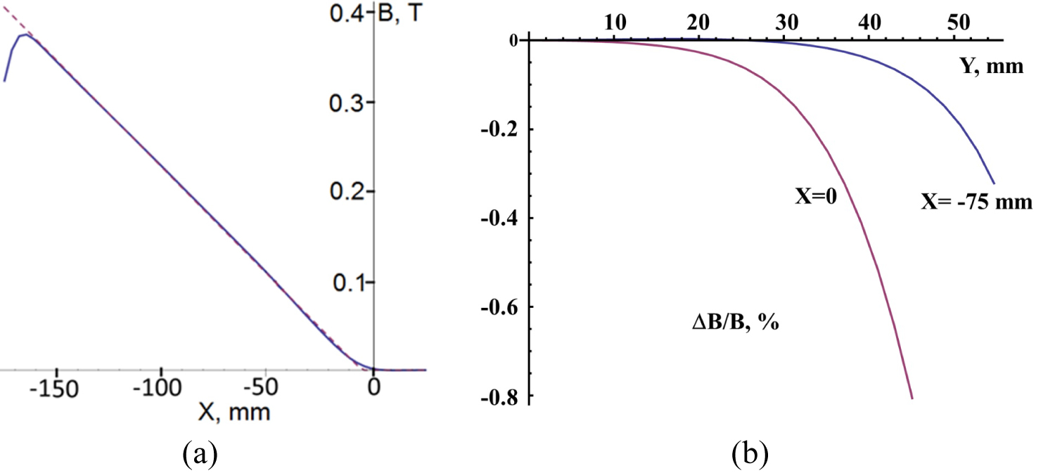
Figure 12: Vertical magnetic field along axis of magnet...
Vertical magnetic field along axis of magnet symmetry [mm] (solid) and ideal alpha-magnet field fit (dashed) at ~ 1 A/mm2 engineering current density (a) The axes labels correspond to that in Figure 10. Relative deviation of the vertical field component [%] related to the field at the axis of symmetry at the same depth in transverse to axis of symmetry direction in median plane at 5/6th (x = -75 mm) and 1/3rd (x = 0) depth of the magnet (b).
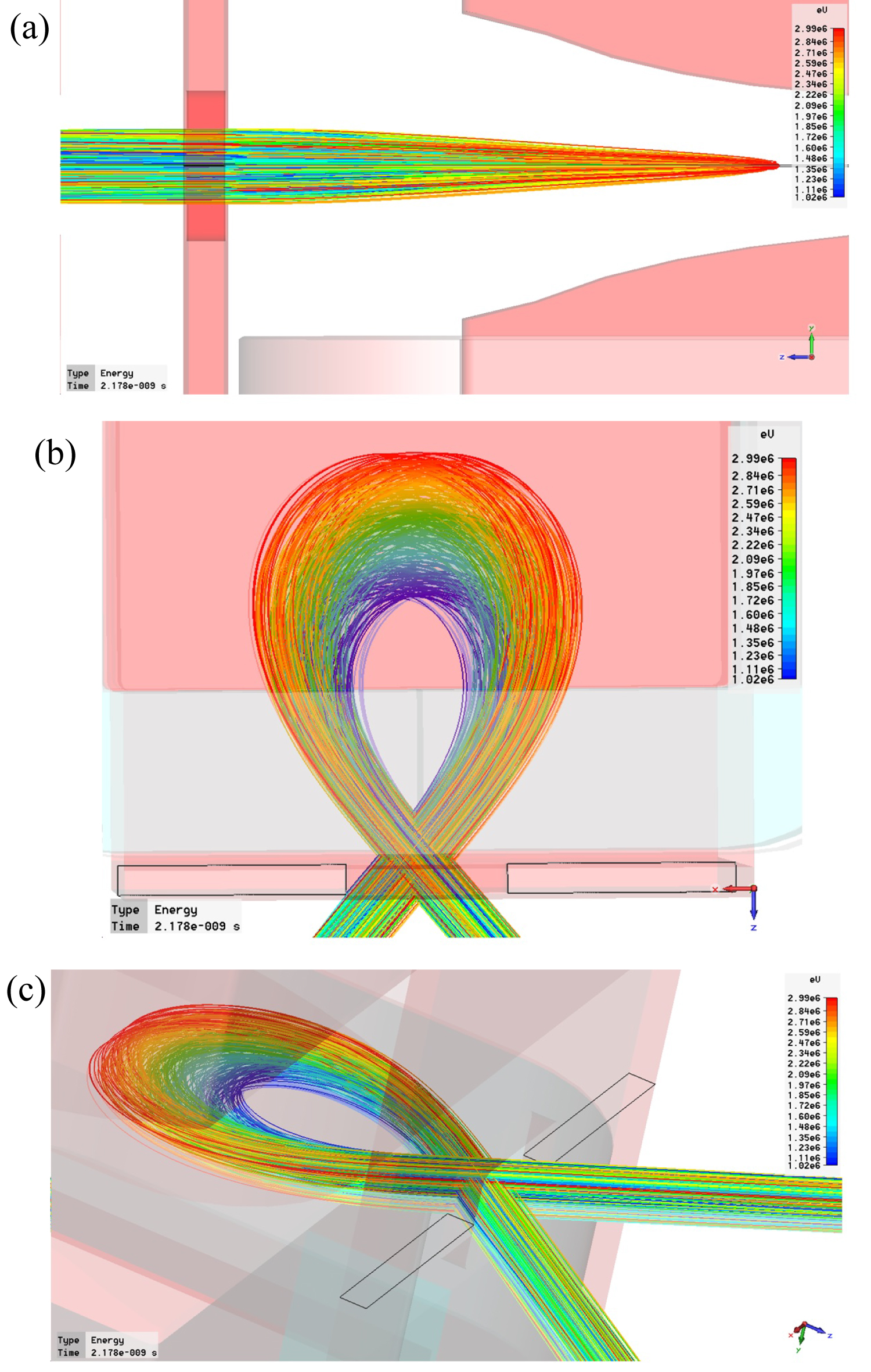
Figure 13: Side (a), top (b) and arbitrary view (c) of...
Side (a), top (b) and arbitrary view (c) of the trajectories simulated for the RadiaBeam α-magnet at energy ranging in (1-3) MeV interval.
References
- GA Westenskow, JMJ Madey, LC Vintro, SV Benson (1986) Owner's manual for the microwave electron gun. HEPL Technical Note. TN-86-1.
- H Hama, NY Huang (2010) Space charge effect for rotation of longitudinal phase space in alpha magnet. Proceedings of International Particle Accelerator Conference, Kyoto, Japan.
- JY Hwang, AP Lee, JH Chen, WK Lau, TH Wu, et al. (2011) A low energy thermionic RF gun linac for ultrashort electron beam. Proceedings of International Particle Accelerator Conference,San Sebastián, Spain, 1081-1083.
- M Borland (1991) A high-brightness thermionic microwave electron gun. Stanford. Ph.D. Thesis. Linear Accelerator Center. Stanford University, Stanford, CA, SLAC-402.
- AV Smirnov (2008) A high performance, FIR radiator based on a laser driven e-gun. In: Viktor P. Nilsson, Photonics Research Developments. Nova Science Publishers, New York, 247.
- VN Volkov, SG Konstantinov, AM Kudryavtsev, OK Myskin, VM Petrov, et al. (2001) Application of autocathode in a superconducting electron RF injector for the industry accelerator. Proceedings of the 2nd Asian Particle Accelerator Conference, Beijing, China, 170-172.
- S Franke, W Ackermann, B Steiner, T Weiland, J Enders, et al. (2008) Integration of fringe field alpha magnets into the V-Code beam dynamics simulation tool. Proceedings of the 2008 Linear Accelerator Conference, Victoria, BC, Canada, 254-256.
- Y Kim, J Gustavsson, P Wang, G Swift, M Emamian, et al. (2006) Commissioning of S-Band RF gun and linac for the Mark-III FEL facility at Duke University. Proceedings of Free Electron Laser Conference, BESSY, Berlin, Germany, 411-414.
- JW Lewellen, S Biedron, A Lumpkin, SV Milton, A Nassiri, et al. (1998) Operation of the APS RF gun. In Proc. of linear accelerator Conf, Linac'98, Chicago, USA, 863-865.
- F Miyahara, F Hinode, M Kawai, T Muto, K Nanbu, et al. (2010) Production of femtosecond electron pulse using alpha magnet together with off-crest acceleration for generation of coherent THz radiation. Proceedings of International Particle Accelerator Conference Kyoto, Japan, 4509-4511.
- VS Skachkov, AN Ermakov, VI Shvedunov (2000) A variable gradient rare earth permanent alpha-magnet. Proceedings of European Particle Accelerator Conference, Vienna, Austria, 2125.
- G Kim, HS Kang (2004) Femtosecond electron beam bunch compression by using an alpha magnet and a chicane magnet at the PAL test linac. Journal of the Korean Physical Society 44: 1223-1228.
- NY Huang, SS Yang, WK Lau, H Hama (2010) Focusing of ultrashort electron bunch for femtosecond inverse compton scattering X-Ray source. Proceedings of International Particle Accelerator Conference, Kyoto, Japan, 1357-1359.
- V Smirnov (2013) Compact scheme for laser-free THz-Sub-THz source. Proceedings of North-American Particle Accelerator Conference, Pasadena, CA, USA, 1421.
- Ph Guimbal, P Balleyguier, A Binet, A Bloquet, D Deslandes, et al. (2002) Status of the ELSA-2 project. Proceedings of European Particle Accelerator Conference, Paris, France, 1768-1770.
- J Saisut, K Kusoljariyakul, S Rimjaem, N Kangrang, P Wichaisirimongkol, et al. (2011) Construction and performance of the magnetic bunch compressor for the THz facility at Chiang Mai University. Nuclear Instruments and Methods in Physics Research A 637: 99-106.
- H Hama, F Hinode, K Kasamsook, M Kawai, K Nanbu, et al. (2008) Space charge effect for short electron bunches in an alpha magnet. Proceedings of Proceedings of Free Electron Laser Conference, Gyeongju, Korea, 305-308.
- S Boucher, R Agustsson, L Faillace, J Hartzell, A Murokh, et al. (2013) Compact, inexpensive X-Band linacs as radioactive isotope source replacements. Proceedings of International Particle Accelerator Conference, Shanghai, China, 3746-3748.
- https://www.cst.com/.
- VS Skachkov (2000) A fixed gradient rare earth permanent alpha-magnet. Proceedings of EPAC, Vienna, Austria, 2122-2124.
- O Chubar, P Elleaume, J Chavanne (1998) Computing 3D magnetic field from insertion devices. J Synchrotron Rad 5: 481-484.
- V Smirnov, R Agustsson, WJ Berg, S Boucher, J Dooling, et al. (2015) Observation of a variable sub-THz radiation driven by a low energy electron beam from a thermionic RF electron gun. Physical Review Special Topics-Accelerators and Beams 18: 090703.
- S Berg, T Barsz, D Briddick, M Givens, G Goeppner, et al. (2003) The advanced photon source injector test stand: Phase two. Proceedings of Particle Accelerator Conference, Potland, Oregon, 2029.
- V Smirnov, R Agustsson, T Campese, Y Chen, J Hartzell, et al. (2015) A table-top alpha-magnet. In Proc of Int Particle Accelerator Conf, IPAC2015, Richmond, VA, USA, 3584-3586.
Author Details
Alexei V Smirnov*
RadiaBeam Technologies, LLC, USA
Corresponding author
Alexei V Smirnov, RadiaBeam Technologies, LLC, 1717 Stewart St., Santa Monica, CA 90404, USA.
Accepted: September 26, 2019 | Published Online: September 28, 2019
Citation: Smirnov AV (2019) On the Magnetic Designing of Compact Alpha-Magnets. Int J Magnetics Electromagnetism 5:022.
Copyright: © 2019 Smirnov AV. This is an open-access article distributed under the terms of the Creative Commons Attribution License, which permits unrestricted use, distribution, and reproduction in any medium, provided the original author and source are credited.
Abstract
Alpha-magnets present unique achromatic properties for beam instrumentation and phase-space manipulation. Nowadays they are acquiring a substantial interest for application in a rapidly growing number of facilities around the world: Free Electron Lasers, far infrared and THz sources, inverse Compton sources of ultra-bright hard X-rays. However, classic design of an alpha-magnet based on hyperbolic poles makes it dimensions large, resulting in significant weight and cost. Several magnetic designs of alpha magnets with reduced dimensions especially for low energy electron beams is considered here including very compact alpha magnets based on permanent magnets with about flat poles as well as compact electromagnetic designs with co-axis coils and substantially non-hyperbolic or truncated poles. These novel design approaches can be applied in relatively small facilities where weight and/or space are limited.
Keywords
Alpha-magnet, Achromatic bend, Magnetic compression
Introduction
An ideal alpha magnet is often presented as half of a quadrupole magnet having constant gradients of the magnetic field in a one half of space and having no fields in the other half of space. A remarkable feature of this unique type of magnet is that it acts as an achromatic magnetic mirror, that is, a parallel (zero-emittance) beam injected at a specific angle to the normal (40.71°) into a perfect alpha-magnet will emerge at the point of injection, at the same angle to the normal and undispersed in momentum. With additional correction coils built-in to the alpha-magnet the angle above can be made 45° [1] instead of the canonical 40.71° by adding a thin dipole magnet, making it, however, no longer precisely achromatic (but quasi-achromatic instead). Particle trajectory has a characteristic alpha-leaf shape inside the magnet allowing so called "magnetic compression" for a momentum-chirped particle beam: higher energy electrons follow longer paths, while lower energy electrons follow shorter ones and thereby leading to shorter bunches at the expense of larger transverse phase space (i.e., phase space rotation, [2,3]). Especially effective application of an alpha-magnet is a sub-ps microbunching of a few MeV electron beam injected from an RF electron gun (or small electron linac, "microlinac") having "natural" energy chirp [4,5]. In that case a sub-ps laser photoinjector is not required and a long laser pulse can be used, or thermionic or cold emission [6] cathode can be used allowing orders of magnitude higher average beam current. Substantial portion of the long RF bunch from the injector cannot contribute effectively into the microbunching in that case. That portion is usually filtered out (typically at low momentums) with a so-called scraper placed inside the alpha-magnet chamber.
A 2 × 45° alpha-magnet is applied for a polarized photoinjector [7] and the first IR Free Electron Laser (FEL) driven by a microwave electron gun [1]. Alpha-magnets with injection provided by an RF electron gun and followed by a linac have been employed at the FEL laboratory of the Duke University [8], the low-energy undulator test line (LEUTL) of the Advanced Photon Source (APS [9]), the far infra-red (FIR) FEL facility of the National Tsing-Hua University in Taiwan [3], coherent THz source in Japan [10], as well as FEL test facilities in France [11], and Korea [12]. Thus alpha-magnets present unique achromatic properties for beam instrumentation and phase-space manipulation. Therefore, alpha magnets acquire a growing interest for application in a rapidly increasing number of facilities around the world: coherent THz sources [5,10], inverse Compton sources of ultra-high brightness hard X-rays [2,13], as well as beam instrumentation for microbunching and phase-space manipulation.
Magnetic chicanes and other combinations of dipole magnets are also used for the magnetic compression (microbunching), but usually they require longer beamline path and so larger footprint to achieve the desired bunch compression. The chicanes are more suitable at higher beam energies (> 5-10 MeV). In addition to the magnetic compression above a combination of an alpha-magnet and conventional quadrupoles may also produce flat beams [14] reducing space charge effects to generate, e.g., coherent Cherenkov radiation [5].
An alpha-magnet allows short beam path compared to, e.g., magnetic chicanes. However, alpha-magnets are usually large (much larger than chicanes), complicated in fabrication, and expensive. The reason is that unlike quadrupole focusing, the "alpha"-leaf trajectory requires much larger volume with magnetic field gradients for given gap implying correspondingly much larger magnet. Classic design of an alpha-magnet is based on hyperbolic poles with correspondingly tilted coils and have large dimensions resulting in significant weight [3,15,16]. Large yoke implies a stacked design composed as a set of plates of a complicated profile. The coils usually require water cooling and high-power supply (multi-kilowatt range).
Below we consider several design approaches for compact alpha-magnets based on light designs with permanent magnets and relatively compact electromagnets.
Alpha-magnets based on permanent magnets
Skachkov, et al. [11] pioneered a remarkably small, light, and simple design of an alpha-magnet with a low gradient based on array of standard-sized blocks (bars) of permanent magnets (PMs). The approach is based on using of tapered magnetization, i.e. different from block to block in the PM array. The magnets in the array usually have the same dimensions. Note, the tapering can be addressed at least partially by varying the height of the magnet (and/or its length). A special routine demagnetization technique [17] has been developed to implement tapering of the PM blocks magnetization. It is somewhat similar to the industrial magnetization applied to the standard PM blocks. The procedure is based on a sequential demagnetization of the PM blocks with a pulsed coil. The corresponding circuitry employs a ballast resistor to limit the demagnetization degree and the capacitor discharge voltage determining the demagnetization magnitude.
A compact microwave injector, such as microlinac [18], may have a considerably lower energy chirp at better beam quality than a conventional 1.5-cell S-band electron gun. That setup would require magnetic compression with a corresponding alpha-magnet having up to an order higher field gradient versus that in the original design (typically ~1-4 T/m for ~1-3 MeV beams) to provide effective microbunching. For example, a C-band variant [5] of a 1.5-cell thermionic injector requires a ~6.8 T/m field gradient at about 7 cm depth and 2.5 MeV beam kinetic energy. Enhanced gradients might be also required at substantial beam currents leading to strong space charge effects [17].
We have applied the same approach [17] to demonstrate feasibility of a ~9 T/m permanent alpha-magnet to produce a 5.4 cm × 3.5 cm "α-leaf" for a ~1.8 MeV energy beam injected from a X-band microlinac [5,19]. To avoid ripples of the field gradient the period of the PM array along the axis of symmetry to be less than the magnetic gap (compare Figure 1 and Figure 2). However, if the magnets are too thin along this direction the cost of the magnetization tapering may become too high. Therefore, we choose the geometric period having substantial fraction of the gap (less than 2/3rd). Square shape used is distributed widely among various vendors of the standard PMs. Vertical dimension of the magnets (i.e., perpendicularly to the trajectory plane) cannot be too small to provide sufficient field strength for the trajectory vertex (especially for the corresponding end magnet). The horizontal dimensions of the magnet assembly (i.e. in plane of trajectory perpendicularly to the axis of symmetry) to be larger than the analytically calculated width and length (or depth) of the α-leaf trajectory respectively by at least 2.5 gaps to provide sufficient field flatness in the widest (or longest) part of the trajectory. In Figure 3 we demonstrate two variants of the design using high grade N52 and low grade 28UH magnets for the PM blocks with 5 × 5 mm2 cross-section. The simulation and in-part optimization was done using magnetic solver of CST Studio Suite code [19]. The magnet dimensions are less than 35 mm × 70 mm × 100 mm. Figure 1 shows a satisfactory field quality in this design. In simulations we achieved > 9 T/m gradient within a 55 mm alpha-magnet depth. For higher maximum fields (and so gradients) a permendure yoke can be used to avoid saturation effect causing field non-linearities. The tapering of the PM magnetization from block-to-block is about linear.
The simulations demonstrated some flexibility of the design: a) The field gradient can be adjusted by varying the magnetic gap [20] or using soft steel plates as an interlayers between the two big PM blocks; b) Insertion of about 1-2 mm soft steel plates on both sides of the chamber (~ 2 mm apart from the PM blocks) is capable to increase the field gradient (and max field) by 24% (see Figure 2); and c) The field gradient can be fine-tuned (decreased by, e.g., ~6% and slightly smoothed) with a thin mu-metal plate insert (see Figure 4). Note the remaining local deviations of the field from ideal profile can be compensated with a conventional shimming technique using smaller "patches" of μ-metal and steel.
A PM-based alpha-magnet can be fabricated avoiding the time-consuming demagnetization procedure. Sufficient field linearity can be achieved with tilted parallelepiped blocks (or set of blocks) with yoke and thin shims. In Figure 5 we demonstrate this new alpha-magnet design concept to achieve almost 12 T/m gradient in about 28 mm depth magnet. The minimum gap between the PM blocks is 2.2 mm. The magnet dimensions are 26 mm × 45 mm × 81 mm. Such a magnet can be applied for a low emittance and as low as 1 MeV energy beam.
We also applied the approach of a tilted-pole magnet to a situation when a much larger trajectory depth is required at higher beam energy. In Figure 6 the alpha-magnet model with 28 cm depth, 2.5 T/m gradient, and 3% field accuracy is shown. The minimum magnetic gap between the PM blocks is 22 mm. The magnet dimensions are 130 mm × 160 mm × 310 mm. The gradient can be tuned in a narrow range by changing the magnet opening angle.
To improve field matching and mitigate fringe fields at the entrance/exit, the magnet of Figure 6 can be supplied by field clamp and window similar to that shown in Figure 3 and Figure 5 and/or using correcting coil and specially profiled mild steel pole instead of the μ-metal shim as shown in Figure 7 or thin dipole shaped as a frame [1].
Thus, the simplicity of the tilted PM approach can be counterweighted by more complicated field matching for magnets having large depth. Nevertheless, both the "tilted" and "demagnetized" concepts indicate feasibility of PM-based alpha-magnets in applications where a wide-range variation of the field gradient is not required.
Magnetic Designing of Compact Electromagnetic Alpha-Magnets
Conventional designs of an electromagnetic alpha-magnet are dominated by essentially hyperbolic pole. The α-magnet configuration is usually similar to half of a quadrupole magnet using windings positioned at 90° (see [1]) or tilted windings [18]. Such a conventional approach provides excellent field accuracy (0.1% for field gradient [18]) but implies a large and massive yoke and coils. Therefore, the yoke is usually composed from stacked iron laminations. That also requires an expensive high-power supply. Additional complications are related to cooling and high inductance of the magnet. On the other hand, in practice it is often more important to make the magnet more compact at somewhat sacrificed field quality (~1%, see [17]).
Here we consider compact designs with co-axis coils and rectangular yoke similar to that used in electromagnetic dipoles. Such an approach implies a pole profile that may essentially deviate from the conventional hyperbolic shape, because the magnetic flux distribution within the core of the pole in such a C-shaped, dipole-like configuration acquires some internal gradient, though may distorted by higher and/or lower order multipoles. For example, significant ripples seen in Figure 2b may produce uncompensated sextupole component. Uncompensated dipole component at the exit and entrance of the magnet derived by transforming of an H-dipole may imply unwanted chromaticity proportional to the deviation from the canonical angle 40.71°.
A special algorithm has been developed to realize this approach resulting to a non-canonical pole shape. The algorithm integrated with the model makes correction of the pole shape on each iteration step using prediction-correction technique to minimize field deviation from linear curve. The correction function is balanced with "weights". It is based on approach of magnetic circuit, in which the gap is considered as an array of parallel magnetic resistors.
We consider two examples of this approach applied to electromagnetic alpha-magnets: a large depth magnet with a moderate gradient, and a magnet with moderate depth, but having a substantial gradient. The Radia code [21] used for the simulations demonstrated exceptional efficiency requiring only several iterations to converge (or to achieve satisfactory field quality). Both magnets can be used as table-top magnets and employ easy-to-fabricate rectangular frame yoke composed from only a few blocks without lamination.
A large-depth, compact electromagnetic alpha-magnet
The large-depth magnet shown in Figure 7 has about twice less height than the magnet in [18] at comparable gap (32 mm vs. 38 mm) and much larger trajectory depth (34 cm vs. 20 cm). The magnet dimensions are 0.5 m × 0.5 m × 0.55 m. The magnetic window made in the clamp for the entrance/exit beam pipes has the following dimensions: 23 cm × 3.2 cm. The magnetic field plotted along the axis of symmetry is shown in Figure 8. The field quality is characterized in Figure 8 and Figure 9.
The magnet optimization enabled very high field quality: maximum field deviation from an ideal magnet of 0.3% and standard deviation of 0.005%. Note the deviations are related to the maximum field along the linear part of the curve (i.e. in the region of high magnetic field, where the particle trajectories are more influenced and so the accuracy is more critical). Standard relative deviation of the field gradient is only 1.6%. Such a field quality achieved in the simulations is comparable to a conventional, much larger magnet with hyperbolic poles (which are usually characterized using the same criterion).
One unique feature of the design of Figure 7 is a nose-like tip of a rather complicated profile on the pole. Such a complicated shape results from compensation of the parasitic (floating) magnetic flux leakage between the pole edge and the filed clamp.
The oscillations of the field gradient deviation seen Figure 9 are a characteristic signature of the magnetic design and especially the optimization method used. The oscillations decay fast for higher fields. The magnitude and period of the oscillations are controlled with the "weight" parameters of the prediction-correction function provided the pole segmentation is sufficient. As it can be seen from Figure 9 the maximum field error occurs in the low field region: at the entrance/exit the field quality is no longer dominated by the poles, but by the fringe fields.
Alpha-magnet design for RBT-APS THz source
Another example of this approach is presented by a magnet designed for a laser-free generation of a sub-mm wave coherent Cherenkov radiation [22] at the injector test stand (ITS) [23] of the Advanced Photon Source (APS) at the Argonne National Laboratory. This experiment was designed jointly by the RadiaBeam Technology, LLC and the APS. Since the magnet has to be deployable on the optical table with existing beamline of the ITS, the specification requirements to the magnet design are rather stringent: 349 mm magnet height (determined by beamline height ~178 mm), 4 T/m maximum gradient (for long-term operation), 15 cm maximum trajectory depth, and ~1% field quality. Application of the approach described above resulted to the magnet design shown in Figure 10. It has 22 mm minimal gap with 16 cm maximum depth and ~10 cm wide good field region. The pole dimensions (projected on median plane) are 125 mm × 177.8 mm. The magnet height, width and length are 34.9 cm, 24.6 cm and 28 cm respectively. The maximum electrical power consumption does not exceed 400 W.
The minimum magnetic gap of 22 mm is resulted from the trade-off between the magnet compactness and capability to insert of a specially designed vacuum chamber [24] profiled to resemble the pole shape. The chamber contains an optical window, two beam ports, a vacuum port, and a moveable scraper to collimate the low energy part of the electron beam. The scraper system is supplied with cooling, beam window, and remotely controlled actuator.
The magnetic field plotted along and transverse to the axis of symmetry are shown in Figure 11.
From the Radia [24] simulations we obtained 1.29% and 0.51% maximum and rms field deviations (related to the maximum field) from the ideal piece-wise linear fit. The magnet efficiency determined from the Radia simulations is 3 Gauss/(Ampere-turn-meter). Note, the gradient limit 4 T/m is imposed by the heating and air convection cooling at room ambient temperature [24]. In spite of compactness the saturation in the yoke do not present the major limiting factor for the magnet performance: the Radia simulations as well as measurements [24] show no significant change of the field quality and efficiency for gradients up to 4.5 T/m, at which the magnet can still operate, though for a limited time. Hysteresis effects are also insignificant for magnet operation [24]. The magnetic measurements of the magnet presented in Ref. [24] confirmed the simulations very well. The measurements indicate 1.3% and 0.63% maximum and rms field deviations (related to the maximum field) respectively with respect to the ideal piece-wise linear fit at the magnet efficiency 3.13-3.16 Gauss/(Ampere-turn-meter).
The results of the electromagnetic design of the compact alpha magnet allowed deploying the magnet on the optical table with challenging form-factor requirements. Simultaneously the design provided operation without water cooling at field gradient, quality, and trajectory depth required by efficient magnetic compression of the 2-3 MeV beam injected from APS S-band thermionic electron gun of the ITS facility. In Figure 12 we demonstrate trajectories simulated with Particle Solver module of the CST Studio Suite [21]. The model designed in Radia code was imported to the magnetic solver and the beam was tracked in the 3D fields of the model. One can see that wedge-shaped profile of the beam (see Figure 12a) caused by vertical focusing allows to design a correspondingly shaped vacuum chamber conformal to the beam and poles vertical profile Figure 13.
Acknowledgements
The author is grateful to Ronald Agustsson and Eduard Spranza for discussions related to the engineering of the last magnet design presented here. The author appreciates validating simulations performed by Dr. Finn O'Shea and Yung-Chuan Chen using Maxwell code and magnetic measurements done by Yung-Chuan Chen that validated the simulations for the RadiaBeam α-magnet design. The author acknowledges Albert Hillman, Shifu Xu and Steven Shoaf for their help with magnet power supplies & controls enabled commissioning of the THz-sub-THz source at ANL/APS/ITS [22]. This work was supported by the U.S. Department of Energy (award No. DE- SC-FOA-0000760).