International Journal of Industrial and Operations Research
(ISSN: 2633-8947)
Volume 3, Issue 1
Original Article
DOI: 10.35840/2633-8947/6505

Article Formats
Throughput Models for a Stand-Alone Vertical Lift Module
Table of Content
Figures

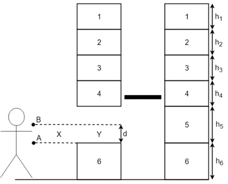
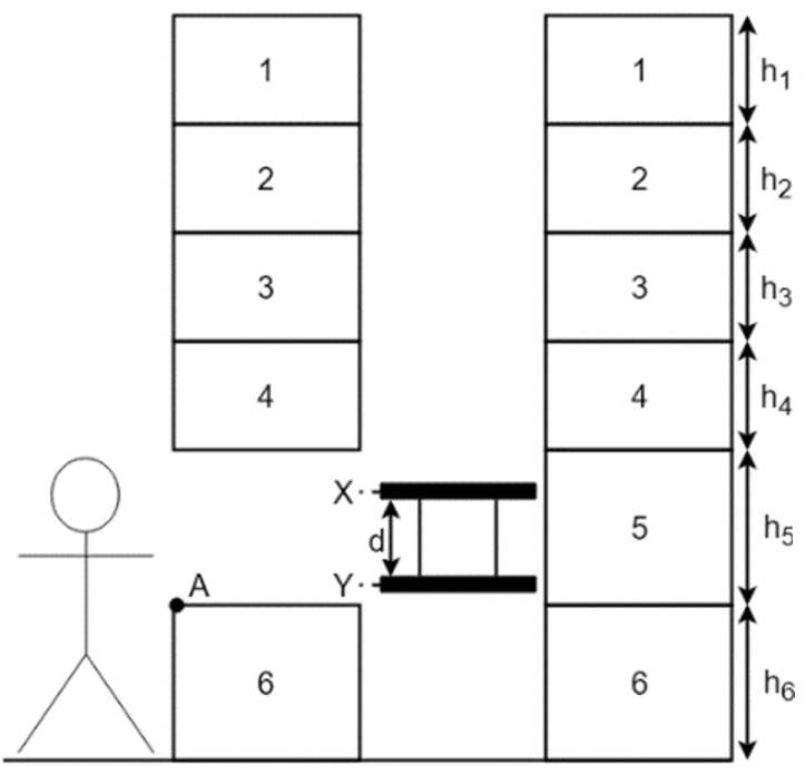
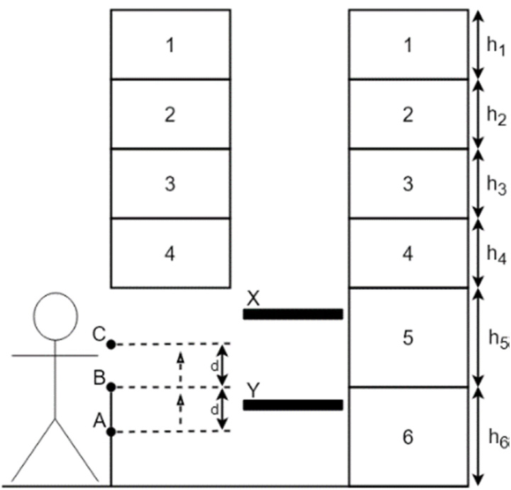
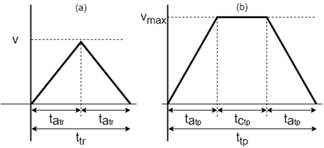
Figure 6: Triangular (a) and trapezoidal (b) speed profile.....
Triangular (a) and trapezoidal (b) speed profile.
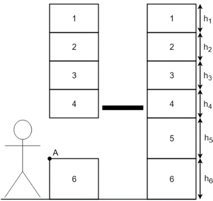
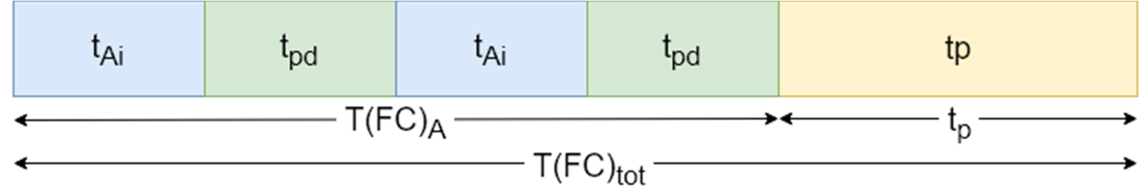


Figure 13: Last command for the dual bay VLM for station A.....
Last command for the dual bay VLM for station A.
Figure 14: First Command for the double extractor VLM....
First Command for the double extractor VLM.

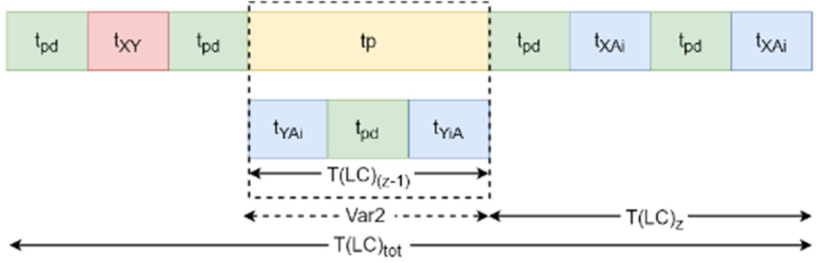
Figure 16: Last command for the double extractor VLM.....
Last command for the double extractor VLM.

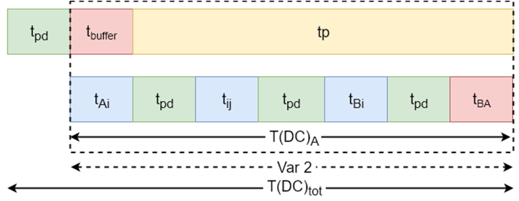
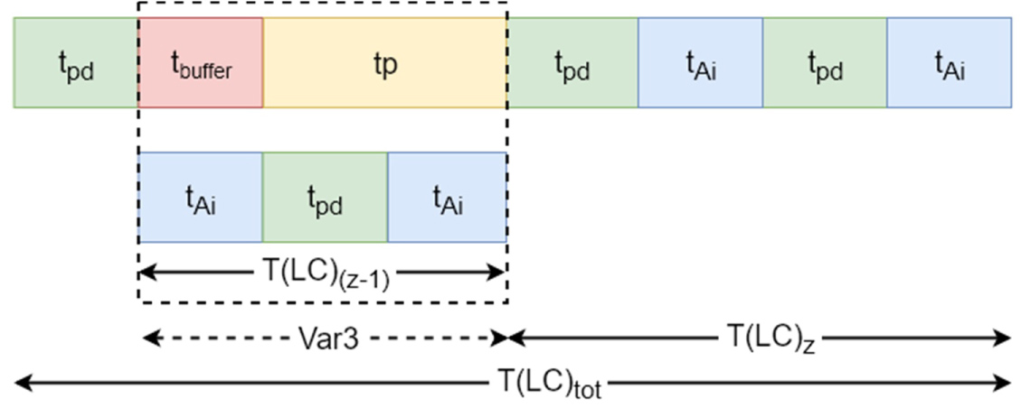
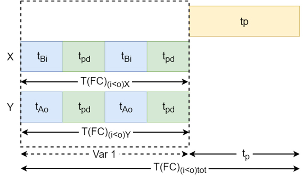
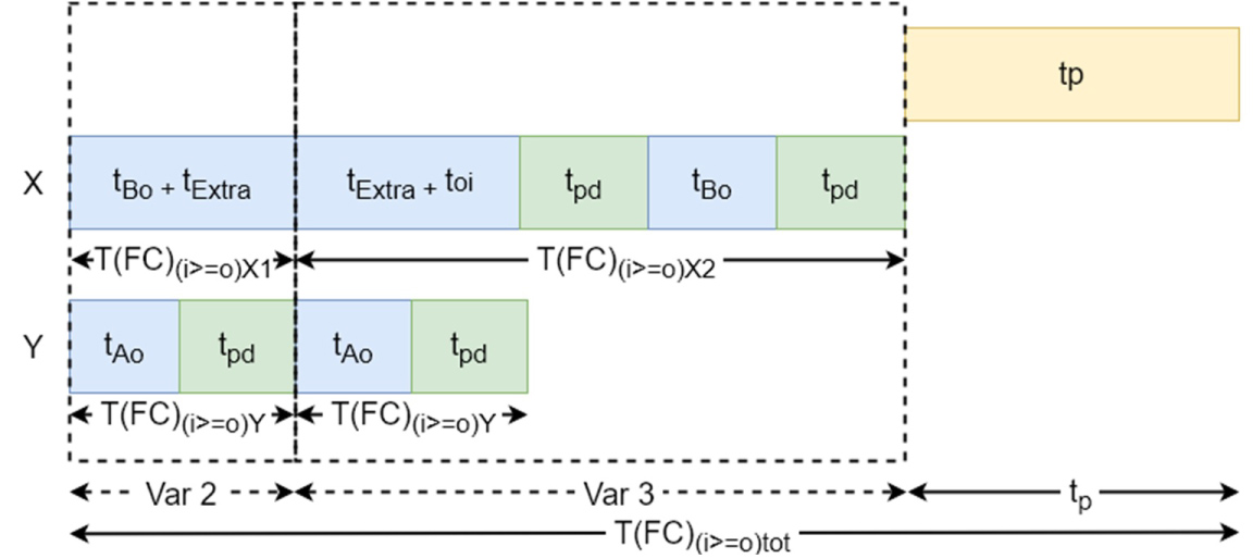
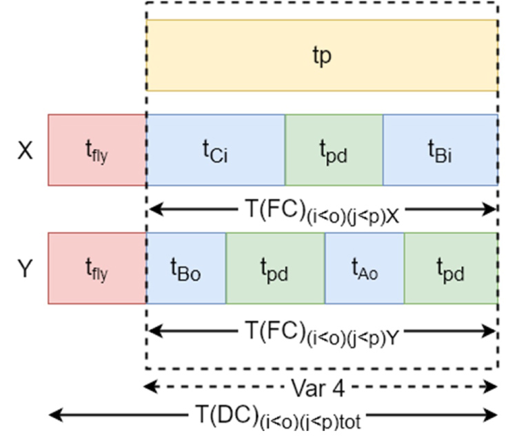
Figure 22: Dual command for dual lift VLM...
Dual command for dual lift VLM for ð'� < ð'œ and ð'� < ð'�.

Figure 20: Dual command for dual lift VLM for....
Dual command for dual lift VLM for ð'� < ð'œ and ð'� ≥ ð'�.
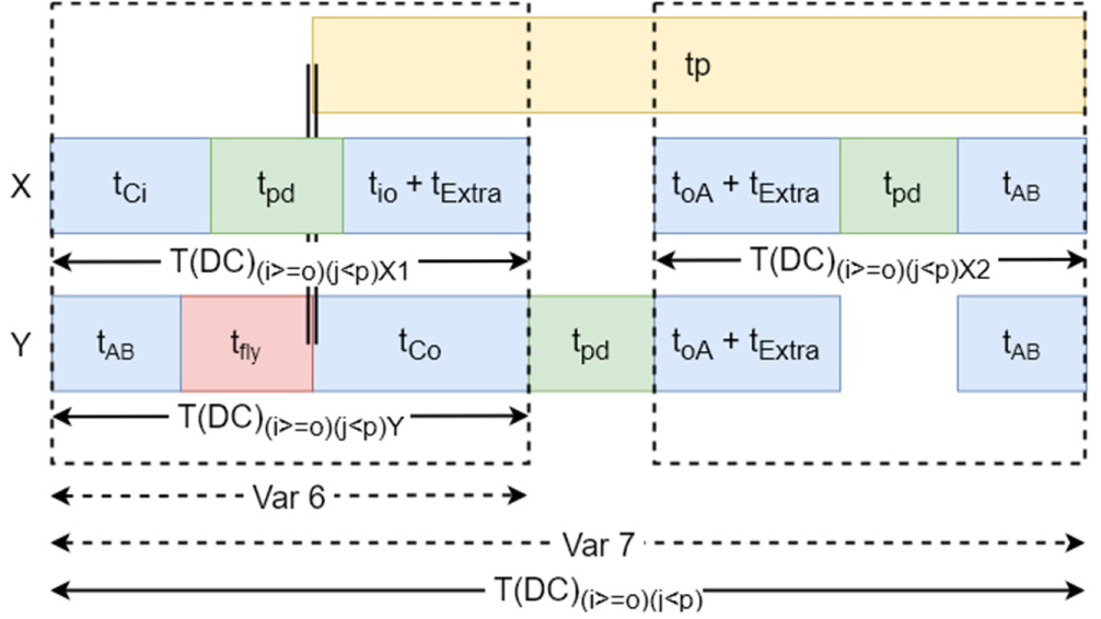
Figure 24: Dual Command for the double lift VLM for...
Dual Command for the double lift VLM for ð'� ≥ ð'œ and ð'� < ð'�.
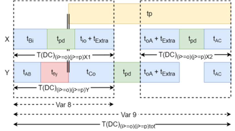
Figure 25: Dual command for the double lift for....
Dual command for the double lift for ð'� ≥ ð'œ and ð'� ≥ ð'�.
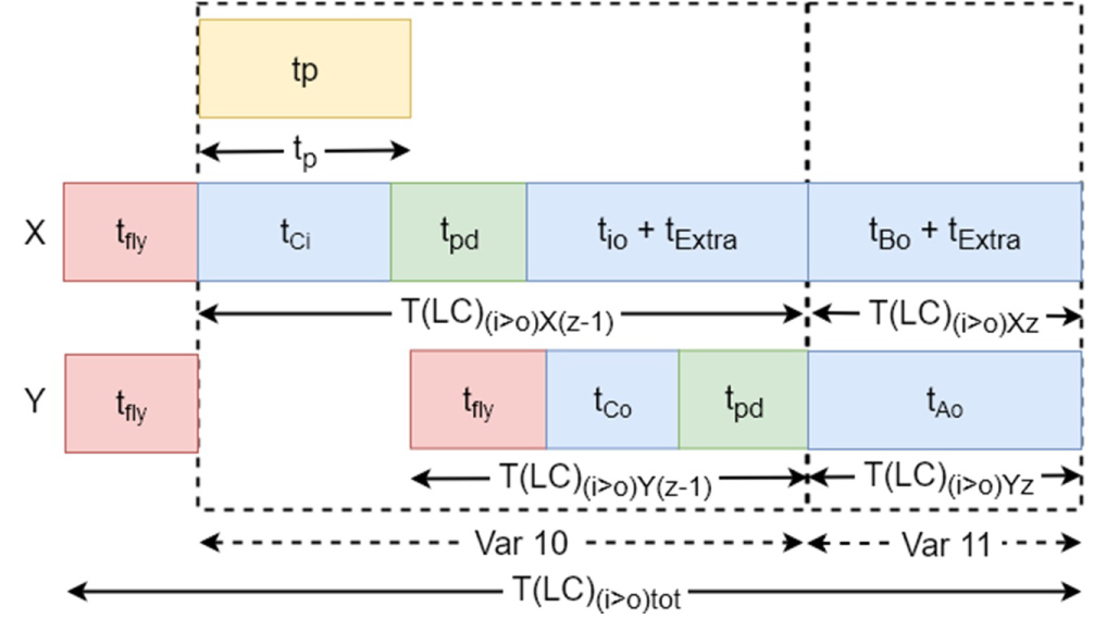

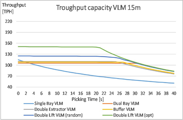
Figure 28: Throughput capacity for all configurations....
Throughput capacity for all configurations with height of 15 m.
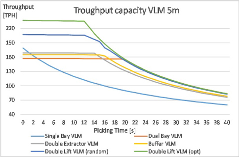
Figure 29: Throughput capacity for all configurations....
Throughput capacity for all configurations with height of 5 m.

Figure 30: Throughput capacity for all configurations...
Throughput capacity for all configurations with height of 10 m.

Figure 31: Throughput capacity for all configurations...
Throughput capacity for all configurations with height of 20 m.
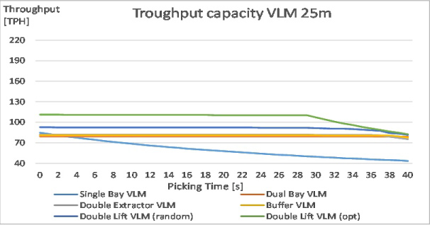
Figure 32: Throughput capacity for all configurations...
Throughput capacity for all configurations with height of 25 m.
References
- R de Koster, T Le-Duc, KJ Roodbergen (2007) Design and control of warehouse order picking: A literature review. European Journal of Operational Research 182: 481-501.
- KJ Roodbergen, IF Vis (2009) A survey of literature on automated storage and retrieval systems. European Journal of Operational Research 194: 343-362.
- D Battini, M Calzavara, A Persona, F Sgarbossa (2015) A comparative analysis of different paperless picking systems. Industrial Management & Data Systems 115: 483-503.
- RD Meller, JF Klote (2004) A throughput model for carousel/vlm pods. IIE Transactions 36: 725-741.
- B Daria, C Martina, P Alessandro, S Fabio (2016) Dual-tray vertical lift modules for fast order picking. 14th IMHRC Proceedings, Karlsruhe, Germany.
- G Dukic, T Opetuk, T Lerher (2015) A throughput model for a dual-tray vertical lift module with a human order-picker. International Journal of Production Economics 170: 874-881.
- HJ Carlo, IF Vis (2012) Sequencing dynamic storage systems with multiple lifts and shuttles. International Journal of Production Economics 140: 844-853.
Author Details
Pieter Vanhauwermeiren1, Marc Juwet1* and Mark Versteyhe2
1Electromechanical Engineering, KU Leuven, Ghent, Belgium
2Electromechanical Engineering, KU Leuven, Bruges, Belgium
Corresponding author
Marc Juwet, Electromechanical Engineering, KU Leuven, Ghent 9000, Belgium, Tel: +32-9-265-87-05.
Accepted: March 07, 2020 | Published Online: March 09, 2020
Citation: Vanhauwermeiren P, Juwet M, Versteyhe M (2020) Throughput Models for a Stand-Alone Vertical Lift Module. Int J Ind Operations Res 3:005.
Copyright: © 2020 Vanhauwermeiren P, et al. This is an open-access article distributed under the terms of the Creative Commons Attribution License, which permits unrestricted use, distribution, and reproduction in any medium, provided the original author and source are credited.
Abstract
Many companies selling products through e-commerce are on the rise. Their products must be stored, picked and send. Most of them do not need huge storage space and consider using a limited number of Vertical Lift Modules (VLM). These companies experience though that the throughput of a standalone VLM is sometimes too low for efficient picking. This paper presents throughput models for both (i) Existing and (ii) New concepts for standalone VLMs, in order for these companies to project future VLM performance. The models are built starting from already existing throughput models for single bay VLMs and dual bay VLMs. They are extended with new available configurations including multiple lifts in a single lift shaft and buffer systems under the picking bay. The models are parametrized so that the influence of VLM height, vertical transport speed and acceleration of trays, transfer time of trays between lift shaft and storage area can be properly assessed. The paper introduces also a novel VLM configuration based on a combination of existing VLMs which proves to have a considerably higher picking capacity. The models show that mainly the effective availability of trays for picking is increased.
Keywords
Automated warehouse, Vertical lift module, AS-RS, E-commerce, Parcel picking, Computer simulation, Throughput model, Picking efficiency
Introduction
Order picking in a conventional warehouse is very time consuming [1]. To reduce the time required for order picking, Automated Storage and Retrieval Systems (AS/RS) were introduced in the 1950s. Since then different types of AS/RS have been developed. A literature overview of AS/RS can be found in [1] and [2]. Also, in e-commerce business picking of goods is an important part of the delivery chain. Large companies can use a variant of an AS/RS. However numerous smaller e-commerce shops can’t afford a large AS/RS. Their typical storage capacity is limited to 20 - 200 mⳠand the number of products to be picked is limited to 100-1000 pieces a day. In case the available floor space is limited, one or more Vertical Lift Modules could be used. Such a VLM (Figure 1) is a semi-automatic warehouse existing of storage racks(up to a height of 30 m) for trays, a lift in between both racks and a picking area (Figure 1). The tray size can vary between 0.5 m by 2 m up to 1 m by 5 m. An extractor is installed on the lift to transport a tray horizontally: In and out the racks, in and out the picking area. The lift transports the trays vertically. Products are picked from the tray in the picking area, most often manually. When picking from a tray is completed, this tray is put back into a storage rack and the next tray is delivered in the picking area.
The major advantage of such a VLM is (i) The small ratio of ground surface to storage capacity and (ii) The flexibility to store all kind of goods.
Since multiple products are in the same tray in front of the picker, there is a potential risk of making picking errors. Recent VLMs reduce the risk of picking errors is by using different technologies to signal the correct product [3].
The major disadvantage of a VLM is the low picking capacity because picking is interrupted while the next tray is delivered to the picking area. The lift speed and the extractor speed have been increased up to their limits and a further significant increase is almost impossible. Especially in case when the picker is picking from a single VLM only, the long tray delivery time can cause an inefficient picking process.
In some cases, the picking efficiency is improved by grouping multiple VLMs in pods and using batch orders [4] and [5]. The operator can then pick from another VLM while the next tray in the picking zone of the previous VLM is delivered. However, the ground surface required and the total investment cost increase with the number of VLMs installed.
Therefore, some VLM manufacturers have developed different VLM configurations in the past years. However, none of them has achieved a throughput of trays that allows for an efficient picking from a standalone VLM.
This paper describes a new VLM configuration, called the Double Lift VLM (DL-VLM). It consists of two independent lifts in the same lift shaft and the picking area exist out of a vertical carousel system, were trays can be stored before, during and after picking. A mathematical throughput model of movement sequences is used to quantify the number of trays that can be delivered in the picking area as a function of picking time.
The mathematical throughput model presented in this paper, is based on an existing model for the single bay (SB) VLM [4] and the dual bay (DB) VLM [6]. These models calculate the displacement time using the maximum velocity. They add a constant delay time to take into account the acceleration and deceleration time. The presented improved model calculates the actual total displacement time taking into account the actual acceleration and deceleration and the maximum velocity. This new model is more accurate especially for short travel distances that tends to occur more frequently if two lifts are used in the same lift shaft. Apart from the single bay and the dual bay VLM, also other existing VLM configurations and the proposed new DL-CP VLM configuration are modelled and compared.
Notations
The basic notations are used for all configurations. For each specific configuration additional notations are added. Those notations are described below:
Basic notations:
H - Total height of the VLM,
hi - Height of section i,
i - Section for the current action of the extractor,
j - Section for the next action of the extractor,
dij - Vertical distance between sections i and j,
dXi - Vertical distance between location X and section i,
dx - Total distance to cover,
dr - Remaining distance to cover,
- Distance travelled during acceleration for moving profile m,
tpd - Time to extract/insert a tray from/onto the extractor,
tp - Average Picking time,
tXi - Travel time from/to location X to/from section i,
tij - Travel time from/to section i to/from section j,
- Time of acceleration/deceleration for moving profile m,
- Time of moving with constant speed for moving profile m,
vmax - Maximum vertical speed of the lift,
amax - Maximum acceleration/deceleration of the lift,
n- Total number of trays that are picked,
z - Last tray that is being picked,
z-1 - Last but one tray that is being picked,
pi - Probability of a storage/retrieval of a tray in section i,
FC - First command,
DC - Dual command,
LC - Last command,
E(FC) - Expected lift travel time for the first command,
E(DC) - Expected lift travel time for each tray in the dual command,
E(LC) - Expected lift travel time for the last command,
T(FC)X - Total time to perform the first command at location X,
T(DC)X -Total time to perform the dual command at location X,
T(LC)Z/(Z-1) - Total time to store the last and last but one tray,
T(FC)tot - Total command time for the first command,
T(DC)tot - Total command time for the dual command,
T(LC)tot - Total command time for the last command,
Ttot - Total time for all the commands.
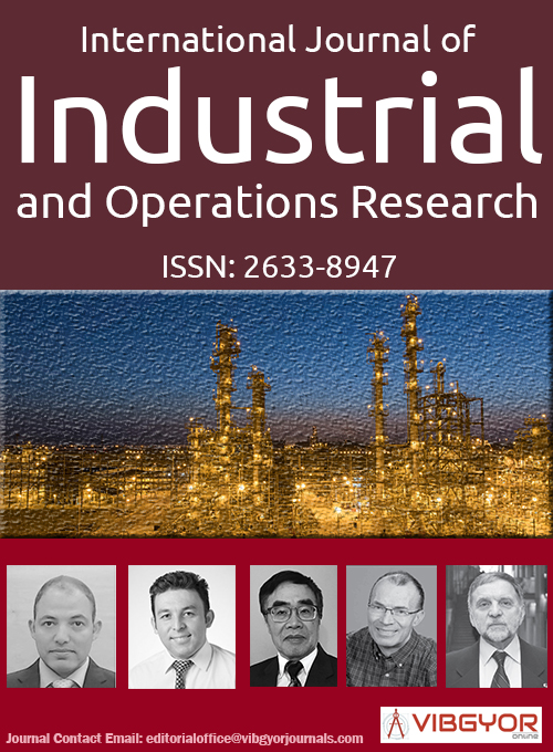
Additional notations for the dual bay VLM are (Figure 2):
d - Vertical distance between picking locations A and B,
tAB - Time to move the lift from picking locations A to B,
tsw - Time to switch trays between positions X and Y.
Additional notations for the double extractor VLM are (Figure 3):
d - Vertical distance between extractor X and Y,
dESi - Vertical distance between pick location S and section i, with extractor E positioned at section i,
dEij - Distance between section i and j, with extractor E positioned at section j,
tESi - Travel time from/to pick location S to/from section i for extractor E,
tESj - Travel time from/to section i to/from section j for extractor E,
tXY - Time to move the lift over the distance d.
Additional notations for the buffer VLM are (Figure 4):
tbuffer - Time to move the buffer one position upwards,
d -Vertical distance between picking location A and B.
Additional notations for a double lift VLM are (Figure 5):
i - Section for the current action of extractor X,
j - Section for the next action of the extractor X,
o - Section for the current action of extractor Y,
p - Section for the next action of extractor Y,
tfly - Time to unload on the fly,
dExtra - Extra distance to avoid collision between the 2 lifts,
d - Vertical distance between locations A and B and between locations B and C,
T(FC)(c)E - Total time to deliver tray with extractor E under condition c for the first command,
T(DC)(c)E - Total time to deliver tray with extractor E under condition c for the dual command,
T(LC)Ez/(z-1) - Total time to deliver and put away the last and second last tray with extractor E for the last command.
Assumptions Mathematical Throughput Models
Creating the mathematical throughput models, 3 assumptions are made, which will be discussed in the next paragraphs.
The first assumption is that no trays are available in the picking zone at the beginning and the end of the operation. The commands are split into three categories: the first command (FC) to take the first tray out of a storage rack and bring it to the pick location, dual command (DC) starting at the movement of a tray from the pick location until the delivery of the next tray at the pick location, the last command (LC) to move the last tray from the pick location to the storage racks. The total time to achieve a throughput of n trays is the time to complete the first, dual and last commands.
A second assumption is that triangular or trapezoidal speed profiles (Figure 6) are used during the displacement. With the average distance between the rack sections and the locations (Appendix A Distance tables) the expected displacement time of the lift for each vertical displacement is calculated with formulas 1-7.
To check if the speed profile is triangular or trapezoidal, the distance travelled during the acceleration with a trapezoidal speed profile is calculated:
When is shorter than , a trapezoidal speed profile is used (Figure 6b). The remaining distance to cover at maximum speed is:
The total displacement time ttp to cover the distance can be calculated out of (1) and (3):
If the maximum speed hasn’t been reached, a triangular profile is used to calculate the displacement time (Figure 6b):
The total displacement time to cover the distance:
Equation (4) or (7) is used to calculate the expected displacement time for each vertical displacement of the lift, under the assumption that all the trays are randomly stored in the VLM sections.
The last assumption is that all of the stored trays are stored randomly in the VLM. To take a tray from a certain section of the VLM, the lift will position at the middle of that section. The probability that a tray is taken from a certain section is based on the dimensions of the VLM (Figure 2, Figure 3, Figure 4, Figure 5 and Figure 7) and are show in Table B1 and Table B2.
Description and Modelling of VLM Configurations
In the next section the different VLM configurations are descripted one by one. First a general description of the configuration is given, then the FC, DC and LC are explained and finally the mathematical throughput models are constructed.
Single bay VLM
The single bay VLM (Figure 7) has 1 pick locations (A), one lift with extractor (X) and 2 storage racks (1-6). In a single bay VLM, the picked tray must be stored to a storage rack before bringing the next tray to the picking location. The lift will wait at the pick location until the picking is done.
During the FC the extractor loads a tray from the storage rack and transports it to the pick location where the tray is unloaded from the extractor and the picking can start. When the picking is done, a series of DC starts. During such a command the picked tray is loaded from the pick location on the extractor, lifted to the required height and stored in the storage rack. The lift then moves to the height of the next tray. This tray is loaded onto the extractor from the storage rack and delivered to the pick location, where the picking can start. This cycle will repeat itself until the last tray is picked. After this the LC begins and the picked tray is loaded onto the extractor and placed in the storage rack. After this the lift is positioned at location A and the LC is finished.
The total time for the commands is calculated based on the expected lift travel time and constant delay times. The expected lift travel time is dependent of the travel time, probability of storage in a certain section and the sections i and j. i is the section used for the current action and j the section for the next action. The probability that an action happens in a certain section are found in Appendix B, Table B1. The distances between the different sections and the pick location are found in Table A1 and Table A2. The travel time is calculated with equations 4 and 7.
First command: The expected lift travel time and the total time for the FC are (Figure 8):
Dual Command: The expected lift travel time and the total time for the DC are (Figure 9):
Last Command: The expected lift travel time and the total time for the LC are (Figure 10):
Total time: The total time to retrieve n trays, with an average picking time tp for each tray:
The number trays per hour (TPH) that can be picked is calculated with the total number of trays that were picked and the total time:
Dual bay VLM
The dual bay VLM (Figure 2) has 2 pick locations (A and B), one lift with extractor (X) and 2 storage racks (1-6). The actual picking is done outside the VLM (Position X) from the 2 picking locations, one at A and one at B. At the inner position Y the next tray can be delivered/picked up to/from the extractor. When transferring a tray from position X to position Y at pick location A, a tray is transferred simultaneously from position Y to position X at pick location B and vice versa. This means that movements on location A and movements on location B take place simultaneously and in opposite directions. As a consequence, actual picking in position X switches from pick location A to pick location B and from B to A. The expected advantage is that the lift travel time and picking time can be partly in parallel. The disadvantage is increased complexity of construction and a transfer time from position X to Y.
During the FC the first tray is delivered at location A, position Y. This first tray switches from position Y to position X and the picking of that tray can start. Simultaneously the lift will retrieve the second tray from the storage rack and deliver it at location B, position Y. After delivering the second tray at location B, position Y the FC is finished and a series of DC will start. In the DC trays have to be loaded on the extractor successively from location A and B, position Y, stored in the storage rack, retrieve the next tray and deliver it successively to location A and B, position Y. The DC will repeat until the last but one tray is picked, after this the LC will start. During the LC, the last but one tray is stored in the storage rack while the last tray is being picked. After completion of the picking, the last tray z is stored in a rack as soon as the lift is available. After this the lift will position back at pick location A. Depending on the location of the last but one tray, the LC will be different. The total time for the last command is the average of the time in case the last tray is picked at location A and in case the last tray is picked at location B.
The total time for the commands is calculated based on the expected lift travel time and constant delay times. The expected lift travel time is dependent of the travel time and the probability of storage in a certain section. i is the section used for the current action and j the section for the next action. The probability that an action happens in a certain section are found in Appendix B, Table B1. The distances between the different sections and the locations are found in Table A1, Table A2 and Table A3. The travel time is calculated with equations 4 and 7.
Cause the picking of one tray and putting away and deliver the next tray are actions that happens simultaneously, the longest time of the two simultaneously actions is the time that will determine the total time. is the longest time of the simultaneously actions.
First command: is the total time to load the first tray from the storage rack and deliver it to location A, is the total time to load the second tray from the storage rack and deliver it to location B. The expected lift travel time and the total time for the FC are (Figure 11):
The total time for the FC is:
With:
Dual command: is the total time to load a tray from location A, position Y on the extractor, put this tray in the storage rack, and deliver the next tray at location A, position Y. Next, a tray is loaded on the extractor from position B, location Y, stored in the rack and delivering the next tray at position B, location Y. This is done during . The expected lift travel time and the total time for picking level A and B are (Figure 12):
The total time for the DC for one tray picked at location A and one tray picked at location B:
With:
The time calculated in (22) is the total time for two trays. Therefore the total time for DC is the average time for location A and location B is:
Last command: is the time to load the last but one tray from a pick location on the extractor and store it at the storage rack. is the time to load the last tray from location A, position X on the extractor and store it at the storage rack. is the same time, but when the tray is loaded from location B, position Y. The expected lift travel time and the total time in both cases for the last but one and last tray are (Figure 13):
The time for the LC for A and B:
With:
The total command time for the last command is the average of and :
Total time: The total time to pick n trays:
The number of trays per hour that can be picked can be calculated using equation 12.
Double extractor VLM
The double extractor VLM (Figure 3) has 1 pick location (A), one lift with 2 extractors (X and Y) and 2 storage racks (1-6) (Figure 3). The 2 extractors are mounted a distance d from each other so the lift can carry 2 trays simultaneously, but the extractors can’t move relative to each other.
During the FC the lift moves to section i to load the first tray on extractor X. The tray is then delivered to pick location A. Once the tray is delivered picking can start and, simultaneously, the second tray is loaded onto extractor X from the storage rack. After loading the second tray, the lift moves until location A is aligned with extractor Y. When the picking of the first tray is done a series of DC starts. During the DC, the picked tray is loaded onto extractor Y. Next extractor X is positioned at location A and the next tray from extractor X is delivered to location A. Picking can start from the new tray. The picked tray, at extractor Y, is stored and a new tray is loaded onto extractor X. The lift then aligns extractor Y with the pick location and wait until picking is done. Now DC is ended, and the LC will start. During the LC the last but one tray is stored while the last tray is picked. After the last tray is picked, this one is put back into the storage rack and the lift returns to start position.
The total time for the commands is calculated based on the expected lift travel time and constant delay times. The expected lift travel time is dependent of the travel time and probability of storage in a certain section. i is the section used for the current action and j the section for the next action. The probability that an action happens in a certain section are found in Appendix B, Table B1. The distances between the different sections and the locations are found in Table A4. The travel time is calculated with equations 4 and 7.
Cause the picking of one tray and putting away and deliver the next tray are actions that happens simultaneously, the longest time of the two simultaneously actions is the time that will determine the total time. is the longest time of the simultaneously actions.
First command: is the time to load the first tray from the storage rack and deliver it to Station A. the time to load the second tray on the extractor. The expected lift travel time and the total time for the FC are (Figure 14):
The total command time for the FC:
With:
Dual command: is the time to unload the picked tray at the storage rack, position extractor X at the next tray, load it onto the extractor and position extractor Y at picking station A. For the dual command, the expected lift travel time and the total time for the DC are (Figure 15):
The total time for the DC:
With:
Last command: is the time to store the last but one tray inside the storage rack. is the time to load the last tray from station A on extractor Y and store it at the storage rack. The expected lift travel time and the total time for the LC are (Figure 16):
The total time for the LC:
With:
Total time: The total time to pick n trays:
Out of the total time and the numbers of tray that have been picked, the trays per hour that can be picked can be calculated with equation 12.
Buffer VLM
The buffer VLM (Figure 4) has one pick location (A), one buffer location (B) under location A, one lift with one extractor (X) and two storage racks (1-6). The buffer location B can hold one tray at a time. Under normal operation trays are always delivered at location B while picking continues from location A. After completion of the picking at location A, the tray from location A is loaded onto the extractor. Then the tray from location B is transferred to location A.
During the FC one tray is loaded from the storage rack and placed at location A and picking can start immediately. The next tray is retrieved from the storage rack and delivered at location B. Then the lift will move to location A and the FC is finished. After the picking is done, a series of DC starts and the picked tray at location A is loaded on the extractor. Then the tray buffered at location B is moved by the buffer system to location A and picking can start. During this transaction, the extractor will store the picked tray in the storage rack and deliver the next to location B. After this the lift will position the extractor at location A and wait until picking is done. Now the DC are finished, and the last command can start. During the LC the last but one tray is stored while the last tray is being picked. After picking is done, the last tray is stored in the storage rack and the lift returns to start position. Now the LC is finished.
The total time for the commands is calculated based on the expected lift travel time and constant delay times. The expected lift travel time is dependent of the travel time and probability of storage in a certain section. i is the section used for the current action and j the section for the next action. The probability that an action happens in a certain section are found in Appendix B, Table B2. The distances between the different sections and the locations are found in Table A1, Table A2 and Table A5. The travel time is calculated with equations 4 and 7.
Cause the picking of one tray and putting away and deliver the next tray are actions that happens simultaneously, the longest time of the two simultaneously actions is the time that will determine the total time. is the longest time of the simultaneously actions.
First command: is the time to load the first tray from the storage rack and deliver it to location A. the time to deliver the second tray to location B. The expected lift travel time and the total time for the FC are (Figure 17):
The total command time for the FC is:
With:
Dual command: is the time to store the picked tray in the storage rack, take the next tray from the rack, deliver it to location B and position the lift at location A. The expected lift travel time and the total time are (Figure 18):
The total command time:
With:
Last command: is the time to store the last but one tray inside the storage rack. is the time to load the last tray from location A on the extractor and store it at the storage rack. The expected lift travel time and the total time for the LC are (Figure 19):
The total command time:
Total time: Out of the total times the total time to pick n trays can be calculated:
Out of the total time and the numbers of tray that have been picked, the trays per hour that can be picked can be calculated with equation 12.
Double lift VLM
The double lift VLM (Figure 5), includes one pick location (B),two buffer locations (A and C), two lifts in the same lift shaft with each one carrying an extractor (X and Y) and 2 storage racks (1-6). Trays are delivered at location A and picked at location B. When picking is completed, the picked tray is moved upwards towards location C. During the upwards movement, a tray can be transferred on one of both extractors that is moving upwards, synchronized with this upwards movement. If transfer is not completed when reaching location C, vertical movement of buffer and extractor stops and transfer continues. The two distances between the three locations are equal. Both lifts with extractor can move independent from each other but cannot pass each other.
During the FC two trays, one with each lift, are taken out of the storage rack and delivered to locations A and B. After the tray at location B is picked, a series of starts. In the DC the picked tray is loaded onto an extractor, while both lift and buffer system moves upwards. This action is called the "on the fly unloading". When the tray is completely loaded onto the extractor the next tray, at location A, has moved upwards and is now at location B. There it is ready to be picked. Meanwhile, one lift will put away the picked tray while the other one will retrieve the next tray and deliver it to location A. This cycle repeats until the last but one tray is picked and the LC starts. During the LC the last but one tray is put away in the storage rack while the last tray is picked. After the picking of the last tray is done, this tray is also stored back in the storage rack and the LC is finished.
The total time for the commands are calculated based on the expected lift travel time and constant delay times. The expected lift travel time is dependent of the travel time and probability of storage in a certain section. i is the section used for the current action of extractor X and j the section for the next action. o is the section used for the current action of extractor Y and p the section for the next action. The possible actions are storing the picked tray or retrieving the next tray. The probability that an action happens in a certain section are found in table. The distances between the different sections and the locations are found in Table A1 and Table A2. The travel time is calculated with equations 4 and 7.
Cause the picking of one tray and storingor delivering the next tray are actions that happens simultaneously, the longest time of the simultaneously actions is the time that will determine the total time. is the longest time of the simultaneously actions.
First command: During the first command only, new trays are retrieved from the storage rack and delivered to location A or B. Therefore both lifts will perform a retrieve command. Section i for extractor X and section o for Y. There are 2 possible FC, depending on the sections: (i) i is higher than o or (ii) i is equal or lower than o.
i is higher than o: When section i is higher than section o (Figure 5), both elevators can retrieve the tray without colliding. So both lifts will position at their section, load a tray and deliver it to location B (for extractor Y) or location B (for extractor X). is the time to perform those actions for extractor X, for extractor Y. The expected lift travel time and the total time are (Figure 20):
The total command time for the first command when :
With:
i is equal or lower than o: When section i is equal or lower than section o (Figure 5), both lifts can collide. To avoid collision, the upper lift moves an extra distance above section o and will wait until the lower lift is finished loading the tray. After this the lower lift will deliver his tray to location A while the upper lift will retrieve his tray from section i and deliver it to location B. is the time to move extractor X above section o, is the time to move extractor X to section i, load the tray and deliver it to location B. is the time to move extractor Y from/to section o to/from location A and load/unload a tray from/to the extractor. The expected lift travel times and total times are (Figure 21):
The total command time for the first command when :
With:
Total command time: The total FC time can be calculated based on all the possible and the probability that an action happens in a certain section.
Dual command: During the DC one new tray is retrieved from the storage rack and delivered at location A, while the picked tray is unloaded from location B and stored back in the storage rack. Both extractors can perform the retrieve or storage actions but only one extractor will perform the retrieve command and one the storage action. The current actions are the actions for the trays that are manipulated at the moment, the next actions are the actions for the next trays that will be manipulated. Depending on the positions of the sections of the current actions and next actions, 4 different dual commands are possible.
Dual command for and : When section i is higher than section o (Figure 5), extractor X will perform the storage action while extractor Y will do the retrieve action. Because section j is higher than section p (Figure 5), extractor X will also perform the storage action for the next action and extractor Y will perform the retrieve action. Both elevators can perform their first action without colliding. is the time to perform the first action for extractor X, for extractor Y. The expected lift travel time and the total time are and the total (Figure 22):
The total command time for the first command when and :
With Var4 the longest time from
Dual command for and : When section i is higher than section o (Figure 5), extractor X will perform the storage action while extractor Y will do the retrieve action. Because section j is equal or lower than section p (Figure 5), extractor X will perform the retrieve action for the next action and extractor Y will perform the storage action. To avoid collision during the next actions, lift X will position above section p, after loading the next tray from section j. Extractor X will deliver the next tray from section o and wait at location B until picking is done. is the time to perform those actions for extractor X, for extractor Y. The expected lift travel time and the total time are (Figure 23):
The total command time for the first command when and
With: is the longest time from , or .
Dual command for and : When section i is equal or lower than section o (Figure 5), extractor X performs the retrieve action while extractor Y performs the storage action for the current actions. Because section j is higher or than section p (Figure 5), extractor X performs the storage action for the next action and extractor Y performs the retrieve action. To avoid collision during the current actions, lift X will retrieve the tray and wait above section o until extractor Y has stored the picked tray. After this, extractor X and Y will move downwards until extractor X is aligned with location A and deliver the tray. Then Extractor X will position at location B while extractor Y will position at location A. is the time to retrieve the tray and position above section o, is the time to move from above section o to location A, unload the tray and position back at location B and is the time to unload the picked try on the fly from location B and position at section o. The expected travel time and the total time for the first command are (Figure 24):
The longest total travel time for the lifts:
With:
The total command time is the longest time between picking and the total travel time:
Dual command for and : When section i is equal or lower than section o (Figure 5), extractor X performs the retrieve action while extractor Y performs the storage action for the current action. Because section j is equal or lower than section p (Figure 5), extractor X performs the retrieve action for the next action and extractor Y performs the storage action. To avoid collision during the current actions, lift X will retrieve the tray and wait above section o until extractor Y has stored the picked tray. After this extractor X and Y will move downwards until extractor X is aligned with location A and deliver the tray. Then extractor X will move above location B while extractor Y will position at location B. is the time to retrieve the tray and position above section o, is the time to move from above section o to location A, unload the tray and position back at location B and is the time to unload the picked try on the fly from location Y and position at section o. The expected travel time and the total time for the first command are (Figure 25):
The longest total travel time for the lifts:
With:
The total command time is the maximum of picking time and the total travel time:
Total command time: The total dual command time can be calculated based on all the possible dual commands and the probability that an action happens in a certain section.
Last command: During the last command, the last 2 trays are stored in the storage racks. First lift X will store the last but one tray in section i. When the last tray is picked, lift Y will store the last tray in section o. After this both lifts will return to their start position. There are 2 possible LC, depending on the sections of the actions: (i) i is higher than o or (ii) i is equal or lower than o.
i is higher than o: When section i is higher than section o (Figure 5), extractor X will store the last but one tray and wait above section o until the last tray from extractor Y is stored to return to start position. is the time to store the last but one tray with extractor X and wait above section o, is the time to store the last tray. and are the times to return both extractors to start position. The expected lift travel time and total times are (Figure 26):
The total command time for the last command when :
With:
i is equal or lower o: When section i is equal or lower then section o (Figure 5), extractor X will load the last but one tray on the fly from the pick location, move above section o and wait until the last tray is stored in section o. Then extractor Y will position at location A and extractor X at section i. The last but one tray will be stored and extractor X will position at location B. is the time to position extractor X above section o, is the time to store the last tray, is the time to move extractor X to section i and store the last but one tray and position al location B and is the times to position extractor Y to location A. The expected lift travel time and total times are (Figure 27):
The total command time for the last command when :
With:
Total time: The total time is the sum of the total command times for each command option and will be different depending on the position of certain sections. Under the assumption of random storage, the chance that a certain section is higher, equal or lower than another section is found in Appendix B, Table B3 and Table B4.
First command: The total FC time can be calculated based on all the possible FC and the probability that an action happens in a certain section.
Dual command: The total DC time can be calculated based on all the possible DC and the probability that an action happens in a certain section.
Last command: The total LC time can be calculated based on all the possible LC and the probability that an action happens in a certain section.
Total time: The total time for the Double Lift VLM:
Out of the total time and the numbers of tray that have been picked, the trays per hour that can be picked can be calculated with equation 15.
VLM Performances
The 5 main VLM configurations are compared by calculating the VLM throughput: The number of trays per hour (TPH) that the VLM can deliver to the picking area. In the comparison underneath the picking station is at a height of 0.8 m, the total height of the picking area is 2 m. The total height of the VLM and the total picking time for each tray are used as variables.
For the double lift VLM two variants for the sequence of the trays to be picked from are calculated. The first variant is called "double lift random" actually meaning that the sequence of trays to be delivered in the picking zone does not take into account the availability of a second lift. The second variant is called "double lift optimized", meaning that the trays are stored randomly but the sequence of the trays to be delivered is optimized. Formulas of paragraph 4.5.4 (i < o and j < p) are applicable.
The throughput results for the five VLM configurations are presented in Appendix C, Table C1, Table C2, Table C3, Table C4 and Table C5 and Figure 28, Figure 29, Figure 30, Figure 31 and Figure 32. The main observation is obviously that throughput generally decreases along the main diagonal of the table, thus if VLM is higher and the picking time increases.
Further observations are:
1. For all heights of a single bay VLM, throughput capacity decreases with picking time. This is quite easy to understand: The average time spent on a tray is the picking time plus the time to fetch and deliver the next tray. There are no parallel actions, meaning that the total average time increases with the height of the VLM.
2. Except for very short picking times, all other VLM configurations perform better than a single bay VLM.
3. The double lift VLM is the best performer for all heights and all picking times even if the sequence of the orders is randomly distributed. Performance is even better if the order sequence is optimized.
4. The throughput models confirm a general feeling among VLM users: If picking time is reduced, e.g. by introducing supporting tools for the pickers, the effective picking capacity increases up to a certain ceiling value. Further reduction of picking times does not further Increase the total capacity. The only exception is a single bay VLM.
5. In case of very long picking times, the picking capacity is almost independent of the height and the configuration of the VLM. The only exception is again a single bay VLM resulting in a considerably lower throughput capacity. This observation is known very well in a more particular case: small products that have to be picked and counted by the picker, can be stored in a high VLM to reduce the storage footprint without further disadvantages.
6. For many product types, picking times are between 8 and 15 seconds/tray. In case of a picking time of 10 s and a VLM height of 10 m, throughput capacity of a single bay VLM is 101 TPH. The capacity of a double lift VLM is 151 TPH and even 183 TPH in case the order sequence is optimized. As a rule of thumb the investment in a second lift for a VLM can increase the throughput capacity by 50%. A further investment in hardware and software to optimize the order sequence can even increase the capacity by 80%.
Conclusion
In this paper the throughput capacity of different VLM configurations has been studied. To this purpose throughput models of these configurations have been built. Also a double lift configuration of VLM has been introduced and studied.
The throughput models can be used to compare VLM configurations on the one hand side and to evaluate the influence of VLM parameters such as VLM height.
Calculations performed so far prove that a double lift VLM considerably increases the throughput capacity compared to a single bay VLM.
Furthermore, it is shown that a reduction of picking times will increase throughput capacity up to a ceiling value. Further investment in picking aids will not contribute to an increased capacity.
Further research should be done to estimate the accuracy of the throughput models presented. This can be done by simulating the VLM movements or by physical testing.
Additionally, the throughput models can be further improved by splitting up the picking time of current models in "VLM waiting time" and "effective picking time". The waiting time depends on distinctive implementations of safety requirements.