International Journal of Astronautics and Aeronautical Engineering
(ISSN: 2631-5009)
Volume 5, Issue 1
Original Article
DOI: 10.35840/2631-5009/7539

Article Formats
Data Acquisition System for Revitalization of Aircraft EMB 312 T-27 and AT-29 Force Simulator
Table of Content
Figures
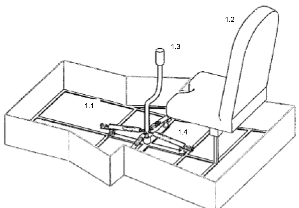
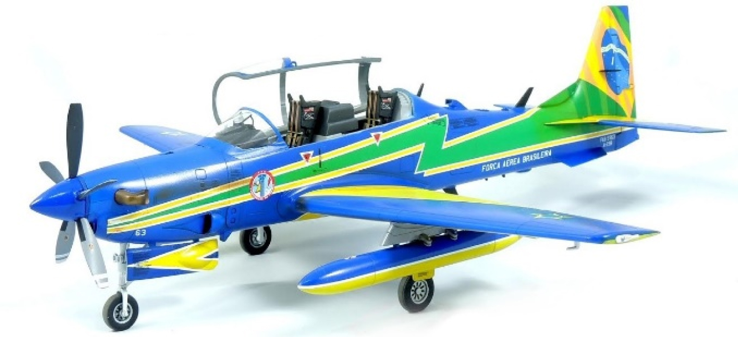
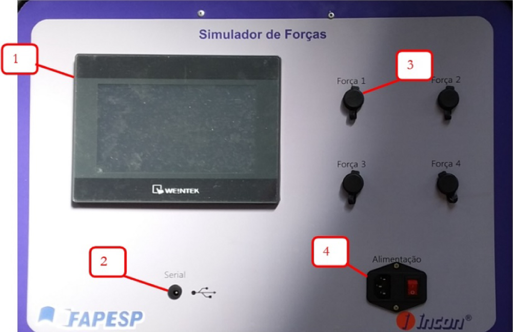
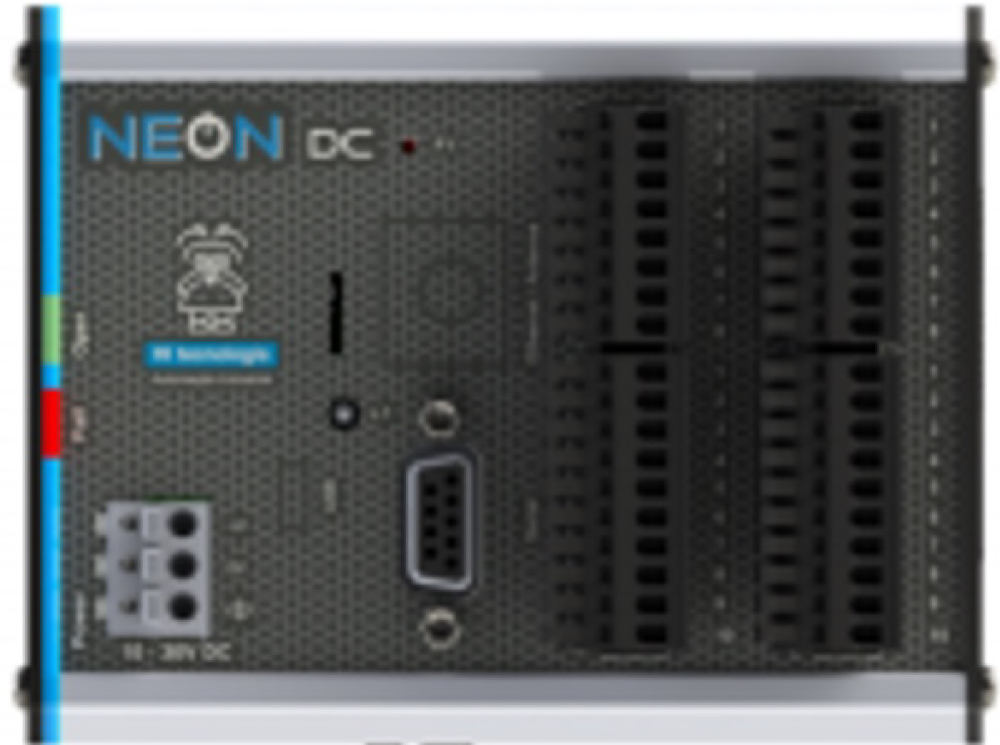
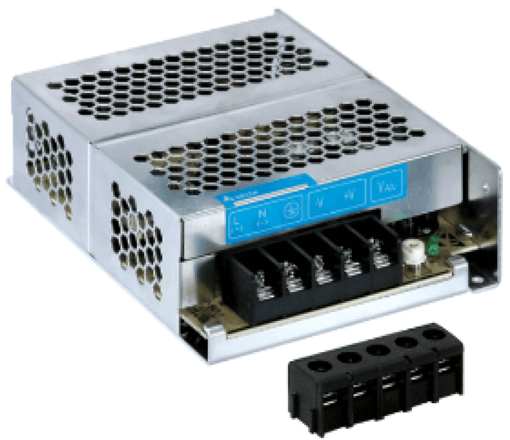

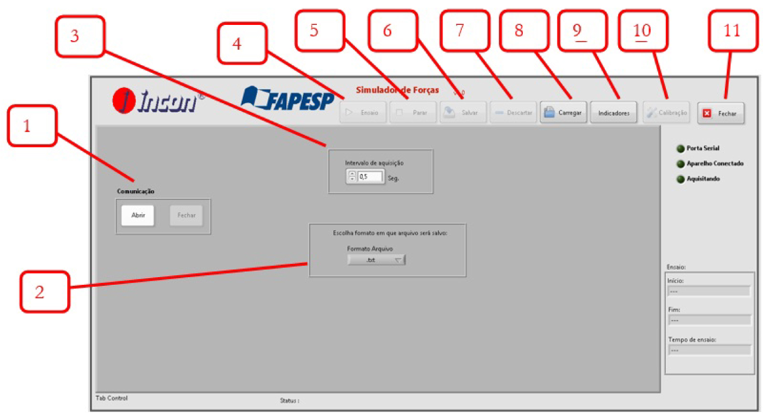
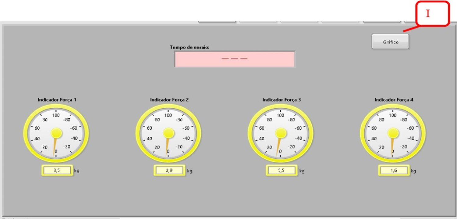
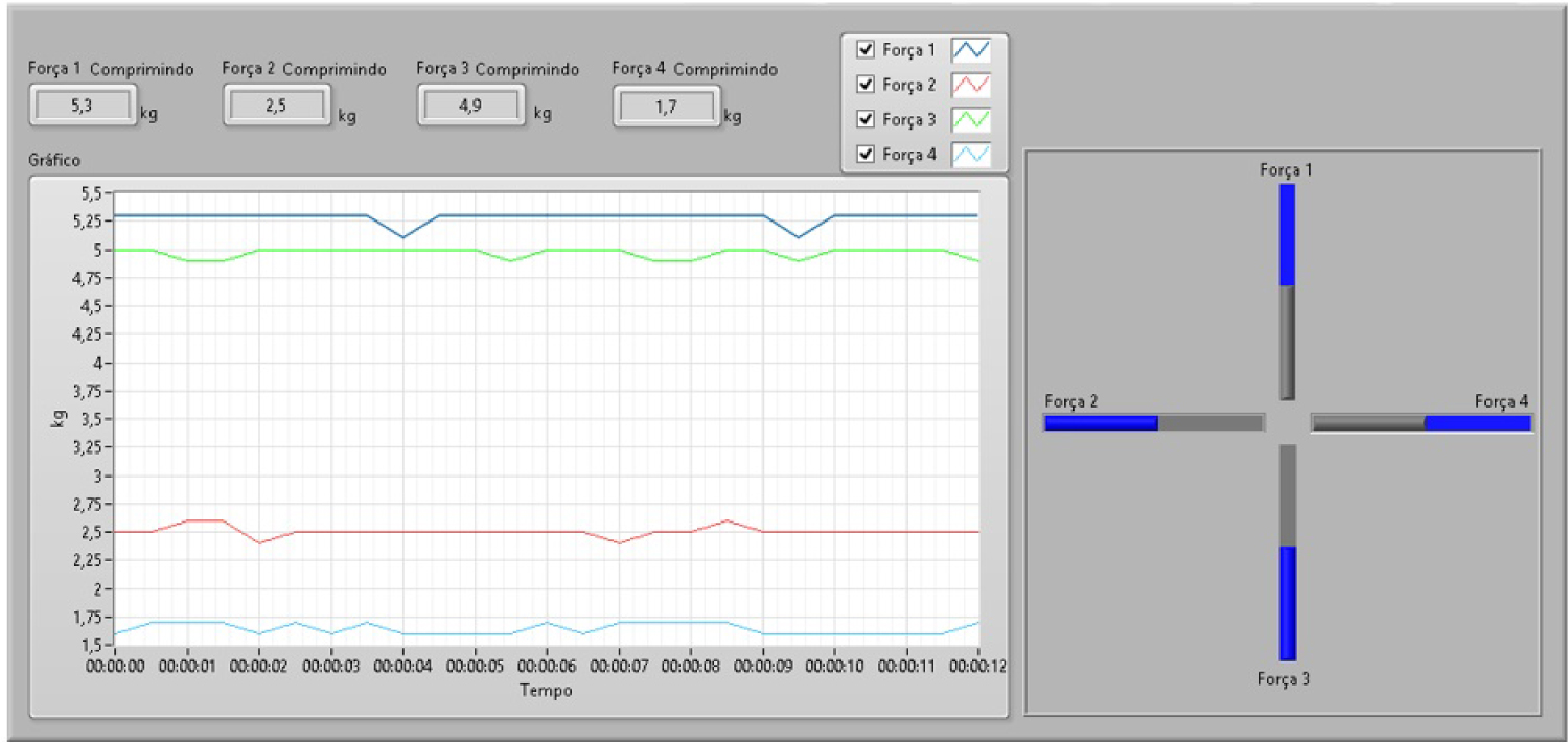
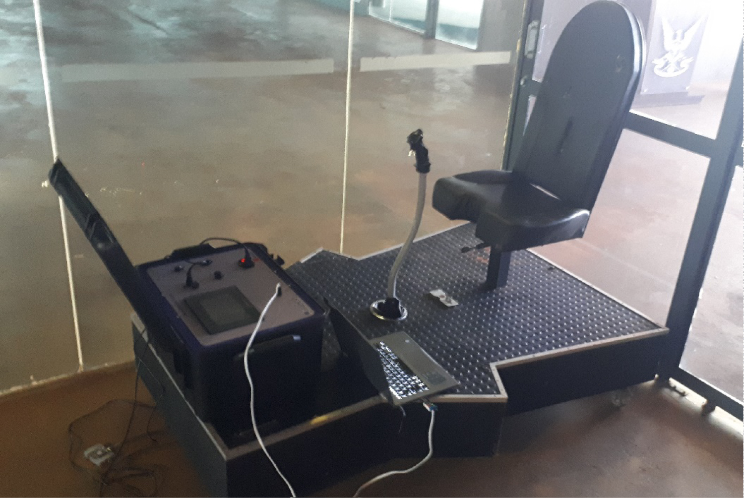
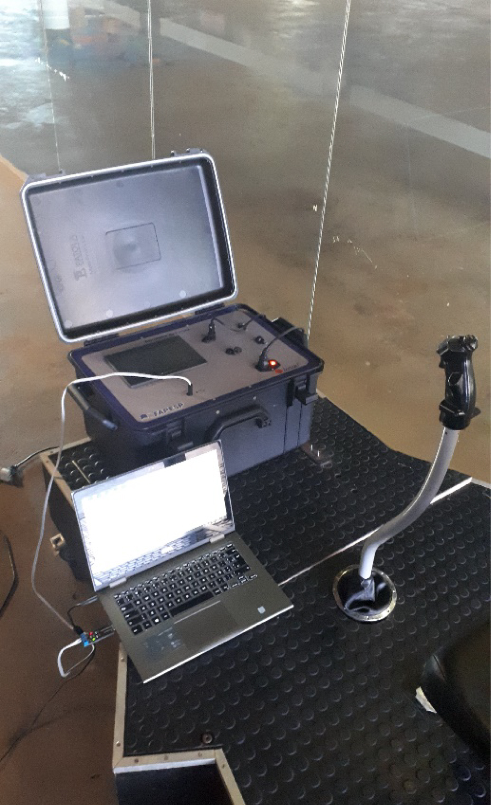
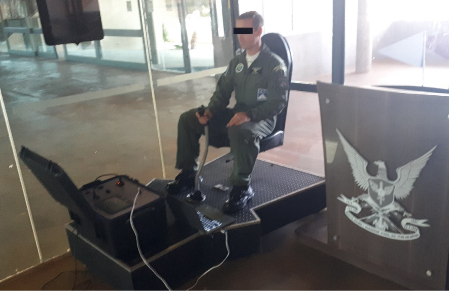
Figure 12: Brazilian air force pilot conducting tests...
Brazilian air force pilot conducting tests on the new version of the force simulator. Source: Autor.
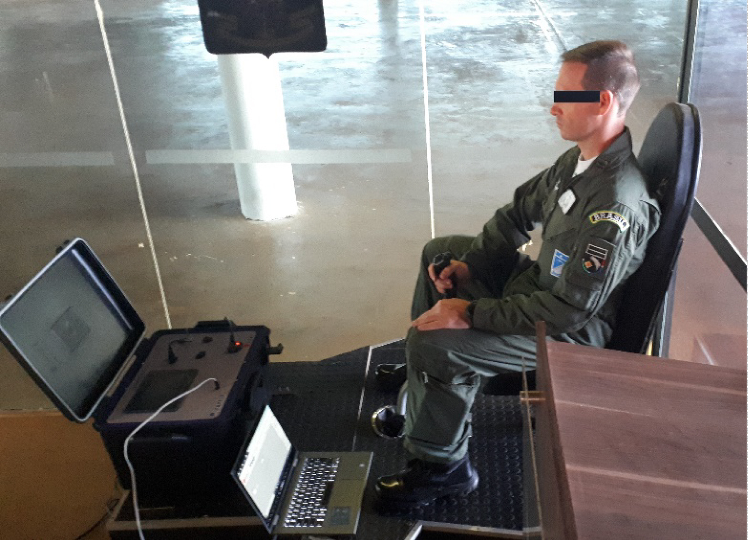
Figure 13: Brazilian air force pilot conducting tests.....
Brazilian air force pilot conducting tests on the new version of the force simulator, side view. Source: Autor.
References
- Bell HH, Waag WL (1998) Evaluating the effectiveness of flight simulators for training combat skills: A review. International Journal of Aviation Psychology 8: 223-242.
- Bezerra TAR, Shimano AC, Campos FAC (2014) Analysis of the forces exerted in flight by aviator cadets of the brazilian air force. Aviation in Focus. Journal of Aeronautical Sciences 2: 61-67.
- Bezerra TAR, Shimano C (2011) Simulador de Forças da aeronave EMB 312 T-27 tucano. Revista Conexão SIPAER 2.2: 45-63.
- Bezerra TAR, Shimano AC, Santiago PRP (2019) Revitalization of the force simulator and adequacy of joystick loads compatible with toucan T-27 and super toucan AT-29 aircraft. International Journal of Astronautics and Aeronautical Engineering 4: 1.
- (1984) Manual EMB 312 T 27. Normas técnicas da aeronave Embraer T-27. Força Aérea Brasileira, Rio de Janeiro, Brazil.
- Martin backer (2012) Manual do assento ejetor: MK8LC. Londres, UK.
- Friedland N, Keinan G (1992) Training effective performance in stressful situations: Three approaches and implications for combat training. Military Psychology 4: 157-174.
- Hays RT, Jacobs JW, Prince C, Salas E (1992) Flight simulator training effectiveness: A meta-analysis. Military Psychology 4: 63-74.
- Izraeli S, Avgar D, Almog S, Shochat I, Tochner Z, et al. (1990) The effect of repeated doses of 30 mg pyridostigmine bromide on pilot performance in an A-4 flight simulator. Aviation, Space, and Environmental Medicine 61: 430-432.
- Lahtinen TMM, Koskelo JP, Laitinen T, Leino TK (2007) Heart rate and performance during combat missions in a flight simulator. Aviat Space Environ Med 78: 387-391.
Author Details
Thiago Augusto Rochetti Bezerra1,2*, Joel Eloi Belo Junior1,2, Shayne de Souza Mattos1,2, Juliana Cristina Viola3, Adriano de Almeida Pereira3, Paulo Roberto Pereira Santiago4 and Joao Paulo Mardegan Issa5
1Graduate Program in Operational Human Performance/PPGDHO, Brazilian Air Force, University of the Air Force, Brazil
2Air Force Academy, Brazilian Air Force, Pirassununga, Sao Paulo, Brazil
3Methodist University of Piracicaba - UNIMEP, Graduate Program in Human Movement Sciences, Piracicaba, Sao Paulo, Brazil
4School of Physical Education and Sport of Ribeirao Preto, University of Sao Paulo, Brazil
5Department of Morphology and Physiology, Faculty of Dentistry of Ribeirao Preto, University of Sao Paulo
Corresponding author
Thiago Augusto Rochetti Bezerra, Graduate Program in Operational Human Performance/PPGDHO, Brazilian Air Force, University of the Air Force, Brazil; Air Force Academy, Brazilian Air Force, Pirassununga, São Paulo, Brazil.
Accepted: June 18, 2020 | Published Online: June 20, 2020
Citation: Bezerra TAR, Junior JEB, Mattos SS, Viola JC, Santiago PRP, et al. (2020) Data Acquisition System for Revitalization of Aircraft EMB 312 T-27 and AT-29 Force Simulator. Int J Astronaut Aeronautical Eng 5:039.
Copyright: © 2020 Bezerra TAR, et al. This is an open-access article distributed under the terms of the Creative Commons Attribution License, which permits unrestricted use, distribution, and reproduction in any medium, provided the original author and source are credited.
Abstract
This article aims to describe the data acquisition system for the Revitalization of the Force Simulator (T-27 and AT-29 Aircrafts). The acquisition system consists of an HMI, a controller/acquirer (clp), 4 signal converters (LC4200), and 4 load cells. The System is supported by supervisory software that records the trials, saving them in txt files. In addition, it is possible to view the quantities graphically. This equipment was developed to measure forces and acquire data on cadets and pilots using a force simulator in a joystick format. Developed with a robust case, with detachable electrical connectors, this is ideal for measurements in the field. The "brain" of this case is the NEON Logic Controller, which reads the inputs provided by the LC4200 that converts signals from the load cells into signals suitable for the PLC. With these readings, it filters and converts the signals to known quantities, in this case force in kgf. In addition, all the information collected by the NEON can be acquired through a serial output (with the help of a serial/USB converter). For this it is necessary to use the supervisory software developed exclusively for this application.The NEON PLC works in conjunction with the MT8071iP Human Machine Interface (HMI) which locally indicates, on an LCD display, the quantities measured in numerical and graphical form to facilitate the operation and handling of the equipment and its functions. The instruments below form part of this equipment:4 load cells Model CSA/ZL-100, from MK Controls, for up to 100 kg of traction and compression.1 NEON PLC with I/O HIO140 module (4 digital inputs (pnp), 4 digital outputs, 4 12-bit analog inputs (0 to 20 mA or 4 to 20 mA), 2 analog outputs (0 to 20 mA or 4 to 20 mA). 1 Expansion module for NEON PLC HIO140, 4 digital inputs, 4 digital outputs, 4 analog inputs 4 to 20 mA or 0 to 20 mA (12 bits). 4 load cell converters, model LC4200, with inputs of -20 to 20 mV and outputs of 4 to 20 mA.
Keywords
Aircraft simulators, Gz force, Load cell
Introduction
The Air Force Simulator (SF) of the T-27 Aircraft (Figure 1) was built between 2005 and 2008, in the Precision Workshop of the Medical Faculty of Ribeirão Preto, University of São Paulo. The objective of this equipment is to develop a simulator of forces exerted in the joystick of the aircraft EMB 312 Toucan T-27 and AT-29 Supertoucan (Figure 2), for evaluation of forces and physical training of pilots and cadets [1-4]. The equipment created simulates, through a joystick and spring system, mechanical forces very close to the actual forces applied to the joystick during the execution of a maneuvers/acrobatics. A system composed of four load cells connected to a signal logger enabled quantification of the forces as a function of time in the simulator [1-4]. This signal encoder module was responsible for filtering and digitizing signals from the load cells. Software integrated with the signal logger was able to store and provide information about the force and moment registers. The signal conditioning was able to provide the varying voltage gain steps, such that the signals from the transducers could be faithfully represented after data collection. The signals applied to each load cell were digitized for subsequent processing in the application. The equipment captured the signals of variation of this applied voltage on the load cells connected to the springs and provided a voltage value corresponding to this action. The simulator can be used as training to strengthen muscle groups required in acrobatic flights and as a tool for physical evaluation and scientific research in Pilots and Aviator Cadets of the Brazilian Air Force during the years 2008 to 2017 [1- 4].
Use of the Force Simulator for Research
The force of gravity is altered many times during an acrobatic flight. A pilot's body weight may increase by 5 to 6 times for a few seconds [5-8]. Consequently the mechanical forces performed by the pilot on the lever, pedals, and joystick are increased. Failure to prepare physically for the flight can lead to muscle and joint injuries and decrease flight safety, increasing the risk of collision with other aircraft, and falls. The force simulator aims to reduce the risk of injury and increase flight safety, by improving the muscle strength of pilots in the movement of the joystick. The principal characteristics of the force simulator are the training of specific muscle groups recruited in flights and the simulation of loads applied to the joystick during the execution of simulated maneuvers [9,10].
This equipment is extremely useful in research at the Air Force Academy. Many of the physiological alterations that pilots undergo during flight can be analyzed in the force simulator without any risk. Studies have already been performed to monitor heart rate, blood pressure, and intracranial pressure using, primarily, physical exertion in the FS [1-4].
Equipment Characteristics
The picture below shows the equipment with the case open (Figure 3):
1) MHI: Interface and display to accompany trials.
2) Serial Connection: Output connection for USB converter that will be connected to the PC.
3) Load cell inputs: Load cell connector.
Power input: with 3 functions:
4) Fuse Holder - Holds protective fuse (2A).
I. On-off key - turns equipment on or off.
II. Socket: Power cord connection.
General technical characteristics
Power supply: 80 to 230 V AC; Consumption: 405 Watts (maximum); Operating Temperature: 10 to 50 °C; Storage temperature: -0 to 60 °C; Relative humidity: 5% to 75% non-condensing; Degree of protection: IP20; Dimensions: 530(L) × 400(D) × 295(H) mm.
Load cell: Load cells are the sensor element for measuring force. The load cells consist of a measuring element where the strain-gages are attached. This element is made of aluminum, meaning that it is very resistant, but also has some elasticity, although minimal. Aluminum steel is slightly deformed under load, but then returns to its initial position, with an elastic response to each load. These extremely small changes (micro-deformations) can be measured by strain-gages. Due to its "S" shape, the cell allows deformation by tensing and compressing. These deformations in the strain-gage are converted to electrical signals. These electrical signals are converted and amplified by the LC4200 load cell converter (described later).
LC4200
The LC4200 is an interface used to convert load cell signals to signals that the PLC can use, in this case, 4 to 20 mA current signals. The equipment has excellent precision and stability, with built-in excitation voltage (10 V) and the presence of external adjustments of zero and span, which allows greater flexibility to adapt to the desired application, and also accuracy, since the adjustments can be carried out in the field. The LC4200 input is a high impedance differential with noise filters, maintaining a quick response to input variations. The minimum possible impedance to be connected to the equipment input is 100 Ω, resulting, for example, from the impedance of a single cell or from the association of cells in parallel. The LC4200 can be conditioned on a DIN rail that guarantees mechanical protection, facilitates installation, and makes direct access to electronic circuit components difficult.
NEON PLC: The NEON PLC (Figure 4) has the role of treating the signals of the load cell converters, converting these signals to kgf and making them available to the HMI and software. The PLC has its own application (software), developed in a Ladder environment. This application was developed in a dedicated and exclusive way for the Force Simulation system. It consists of a single rack with capacity for up to 2 I/O modules, HIO140.
HMI MT8071iP: The main role of the Human Machine Interface is to show the force data calculated by the PLC. The device has its own software developed for this Force Simulator application.
Filter: The filter is used to prevent electromagnetic noise and interference, propagated by the electrical network, from propagating to the electronic components (converters, clp, HMI, etc.) of the Force Simulator System.
USB converter: The model 1S-USB-485 converter allows installation of an RS485 serial output (COM port) on a PC via an available USB port. This converter has all the control signals for a standard serial RS485, including optional terminator enabled via dip switch. This connection allows communication between the PC (through supervisory software) and the PLC.
24 V Power Supply: Serves as an auxiliary power supply (Figure 5) for the Human Machine Interface.
Description of Neon Plc Operation Software
PLC Software details
The software in the PLC (controller) treats each signal input and transforms it into an engineering unit (kg). The way this is done is described by the equation below:
Y = m X + n + tara
Where:
Y→ force in kg
X→ analog input (in engineering units, 0 to 4095)
Tara→ Adjustment value of "zero" (described below)
m and n → Variables of the equation of the line. If necessary, the supervisory software helps to calculate these numbers.
To avoid fluctuations in the reading signal, already converted into kg, a digital filter was programmed. Digital filter:
Yn = (1-α). Xn + α. Y(n-1)
Where:
Yn→ current force value
Xn→ current input value
Y(n-1) → previous force value
α→ filter (%) The value of α is the same for the 4 analog inputs.
The "Tara" routine works in a similar way to normal scales (butchers, for example). When active, it takes the current value of force (weighing) and considers it to be "zero" for all other measurements.
Operation
Operating the case is very simple. First it needs to be turned on by connecting it to the mains (127 or 220 V). Connect the cables to each load cell. Then activate the on/off switch. It is possible to operate the instrument without the software just by observing the force values on the display. If you want to operate with the help of the software, connect the converter to the PC and the cable to the instrument case. For more information on using the software, read chapter 5 below. The case display is touch screen (Figure 6), with no physical buttons.
1. Indicators: Numerically show the forces in each load cell. A negative indication is the load cell being compressed. A positive indication is the load cell being pulled.
2. Clocks: Indication of forces in the load cell shown on a clock. Negative values express the cell being compressed.
3. Tara key makes the current value "zero". It needs to be pressed for 2 seconds to activate. To disable, press for 2 seconds.
4. Status LED: Indicates HMI and controller working.
Supervisory Software
When you run the software, it has the following initial screen:
This is the screen (Figure 7) where the user connects the software to the equipment. This is also the screen where the format in which the trials will be saved is configured and the rate of acquisition of the trials is configured.
1. Communication: Buttons to connect or disconnect software from the case.
2. Serial port opened correctly. If this LED does not light up, make sure that the USB/serial converter has been connected correctly. Also make sure that the converter driver has been installed and that the COM port has been configured correctly (see chapter 5.2 COM file format: Choose the format in which the trial will be saved (.txt or .xls).
3. The two options are .txt and xls (Excell).
4. Acquisition Interval: Sets the frequency with which the points will be saved during the trials, that is, the rate of acquisition of the points in the trial.
5. Trial: Start trial. This key is only enabled if the software is connected to the instrument case.
6. Stop: Ends trial. This will only be enabled when a trial is in progress.
7. Save: Saves trial on the computer. This will only be enabled after starting a trial and stopping it.
8. Discard: Discard trial started. This will only be enabled after stopping a trial.
9. Load: Load trial file saved on the computer. First the operator is asked which file (already saved, see "Save"). Then the screen below is opened:
10. Indicators: Moves to the indicators screen. Returns to the Indicators screen (Figure 8). Use this key when you are in the middle of a trial, on the graphic screen and want to return to the numeric indicators.
11. Calibration: Opens the calibration screen for the analog load cell inputs. Software connected to the device. If this LED does not light up, make sure the serial cable is correctly connected to the case, the case is on, and the serial port is opened correctly (item above). Once connected, the software will automatically jump to the indicators screen (Figure 9, Figure 10, Figure 11, Figure 12 and Figure 13).
The configuration screen has the following features and functions:
I. Inputs: These fields show the current value (read directly from the controller) of the analog inputs (Xn) and the values converted to force (Yn).
II. Filter: The first indicator is to show the current value of the digital filter of the analog inputs. The second indicator is the control to set a new value for the filter. The "Write" key updates the controller with the new filter value.
III. Reset: Returns the controller calibration to factory values.
IV. Calibrations: Fields to configure each analog input individually.
a) Input Unit: Fields for adjusting the highest and lowest input values (in physical units), in the case of kg. For the current case the value must be from -150 to 150 kg.
b) Engineering unit: Analog input value. Input value must be from 0 to 4095.
c) Calculated Values: Calculated calibration values.
d) Calculates: Calculates the calibration values based on the factors entered (items a and b).
e) Close: returns to the calibration screen.
Conclusions
The T-27 simulator, developed in 2008, and its revitalization completed in 2020, is projects for the physical training of pilots and aviation cadets of the Brazilian Air Force. The new version of the force simulator, in addition to inserting the new system for collecting and evaluating force data, also includes the possibility of simulating the force applied to the stick of the AT-29 Supertouncan aircraft.
Acknowledgement
The Authors would like to acknowledge grant#2018/02106-4, Sao Paulo Research Foundation (FAPESP).